Published 4-20-2015, Control # 502-01 2-43
RT540E SERVICE MANUAL HYDRAULIC SYSTEM
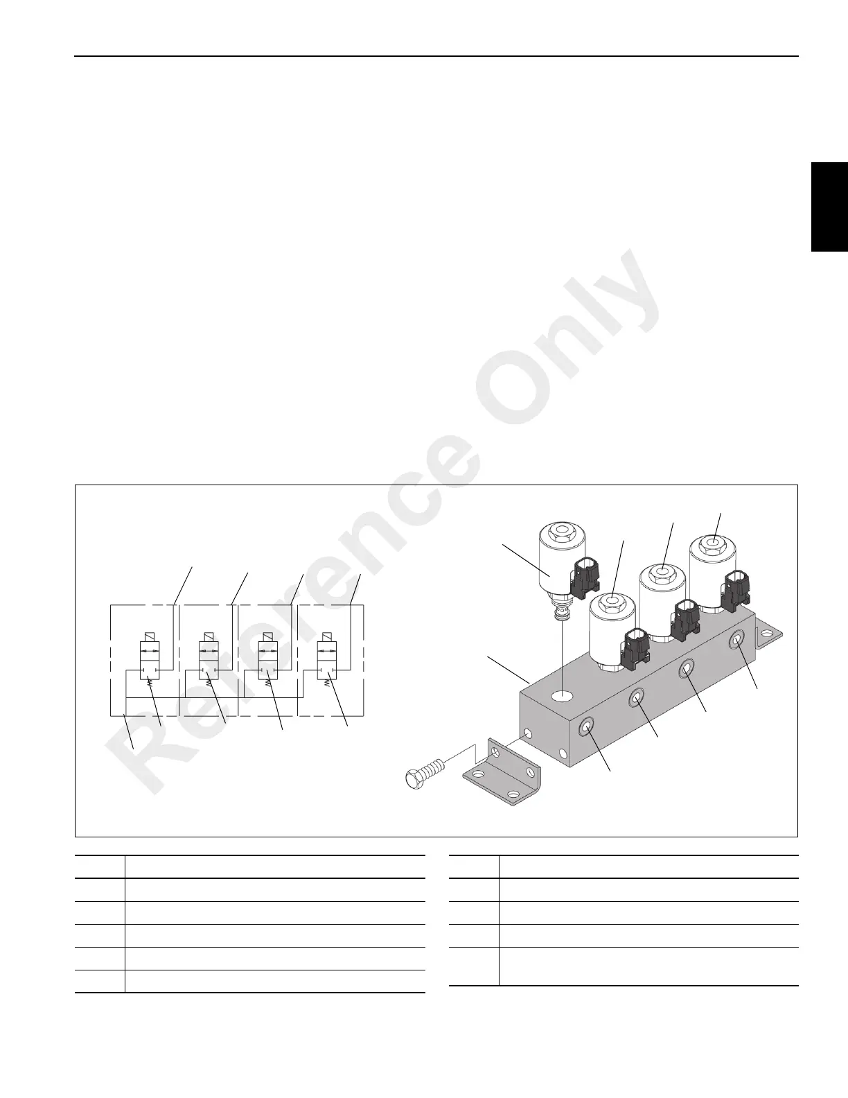
OUTRIGGER CONTROL MANIFOLD
Description
There are two outrigger control manifolds utilized on the
crane, one for the front outriggers and one for the rear
outriggers. The manifold consists of four normally closed two
position two way solenoid valves (Figure 2-22). They are
mounted inside the frame of their respective outrigger box.
When energized, the solenoid shifts the spool to open
allowing extension or retraction of the outrigger cylinders.
Maintenance
Removal
1. Tag and disconnect the hydraulic lines to the solenoid
valves; cap all lines and openings.
2. Tag and disconnect the electrical connectors.
3. Remove the capscrews, nuts, lockwashers and
flatwashers securing the manifold to the outrigger box;
remove the manifold.
Inspection
Visually inspect the valves and hydraulic connections for any
evidence of leaks or other damage. Check security of the
electrical connections. Inspect the wiring for any evidence of
cracks or breaks.
Installation
1. Position the manifold on the mounting and secure with
the lockwashers, flatwashers, nuts and capscrews.
Torque capscrews see Fasteners and Torque Values,
page 1-11.
2. Connect the electrical connectors to the solenoids as
marked during removal.
3. Connect the hydraulic lines to the valves as marked
during removal.
Functional Check
Activate the hydraulic system and cycle the affected
cylinder(s) several times. Observe for proper functioning of
the affected cylinder(s). Ensure the solenoid valve hydraulic
connections are secure.
1
2
3
4
5
5
4
3
2
FIGURE 2-22
6544-1
6544-2
1
6
7
8
9
9
8
7
6
Item Description
1 Solenoid Valve - Left Front or Rear Extension Cyl
2 Solenoid Valve - Left Front or Rear Jack Cylinder
3 Solenoid Valve Right Front or Rear Jack Cylinder
4 Solenoid Valve Right Front or Rear Extension Cyl
5 Outlet Port - Left Front or Rear Extension Cyl
Item Description
6 Outlet Port Left Front or Rear Jack Cylinder
7 Outlet Port Right Front or Rear Jack Cylinder
8 Outlet Port Right Front or Rear Extension Cyl
9
In Port (Far Side) - From Port B of Outrigger
Selector Valve
Reference Only

 Loading...


