HYDRAULIC SYSTEM RT540E SERVICE MANUAL
2-42 Published 4-20-2015, Control # 502-01
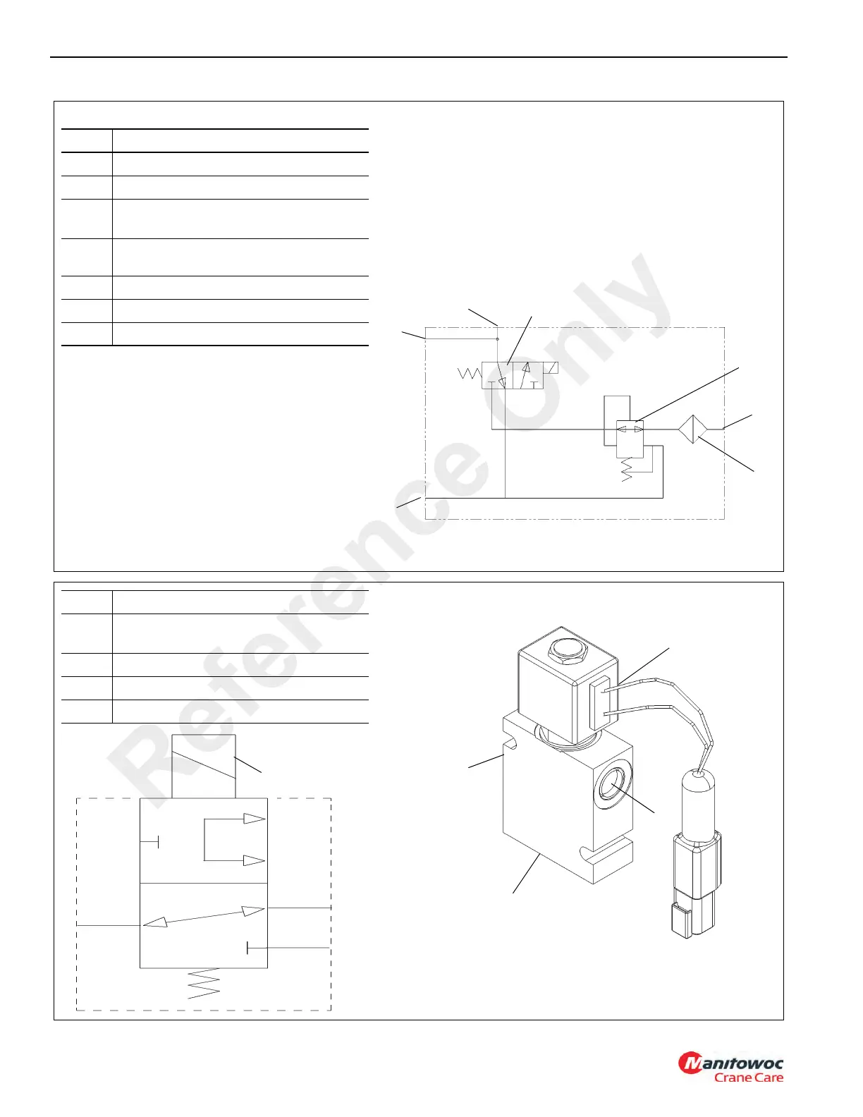
FIGURE 2-20
1
4
3
Item Description
1 Three-Way Solenoid Valve
2 Pressure Reducing Valve
3
Port P - From Pressure Port On
Transmission
4
Port C - To Differential Lock Actuator On
Axles
5 Port T - To Tank Port On Transmission
6 Port G - Gauge Port
7 100 Mesh Screen
2
6718-2
Hydraulic Schematic
6
5
7
FIGURE 2-21
1
4
3
Item Description
1
Port 1 to Front and Rear Axle Differential
Lock Actuators
2 Port 2 to Park Brake/Shift Valve Port T
3 Port 3 to Park Brake/Shift Valve Port P
4 Solenoid Valve (Connector not shown)
2
7011-2
Hydraulic Schematic
4
2
1
8473
3
Reference Only
 Loading...


