Published 4-20-2015, Control # 502-01 3-1
RT540E SERVICE MANUAL ELECTRIC SYSTEM
SECTION 3
ELECTRIC SYSTEM
SECTION CONTENTS
Description . . . . . . . . . . . . . . . . . . . . . . . . . . . . . . . 3-1
General. . . . . . . . . . . . . . . . . . . . . . . . . . . . . . . . . 3-1
Alternator . . . . . . . . . . . . . . . . . . . . . . . . . . . . . . . 3-1
Batteries . . . . . . . . . . . . . . . . . . . . . . . . . . . . . . . . 3-1
Fuse Panel . . . . . . . . . . . . . . . . . . . . . . . . . . . . . . 3-2
Relays. . . . . . . . . . . . . . . . . . . . . . . . . . . . . . . . . . 3-3
Maintenance . . . . . . . . . . . . . . . . . . . . . . . . . . . . . . 3-4
General. . . . . . . . . . . . . . . . . . . . . . . . . . . . . . . . . 3-4
General Troubleshooting . . . . . . . . . . . . . . . . . . . 3-4
Troubleshooting Swivel-Caused Electrical
Problems. . . . . . . . . . . . . . . . . . . . . . . . . . . . . . . . 3-4
Connector Troubleshooting . . . . . . . . . . . . . . . . . 3-4
Troubleshooting Engine Starting Problems . . . . . 3-5
Troubleshooting Engine Charging Problems . . . . 3-5
Troubleshooting Accessories. . . . . . . . . . . . . . . . . 3-6
Alternator Replacement. . . . . . . . . . . . . . . . . . . . . 3-7
Starter Replacement . . . . . . . . . . . . . . . . . . . . . . . 3-7
Battery Replacement . . . . . . . . . . . . . . . . . . . . . . . 3-8
Relay Panel Component Replacement . . . . . . . . . 3-8
Rocker Switch Replacement . . . . . . . . . . . . . . . . . 3-8
Ignition Switch Replacement . . . . . . . . . . . . . . . . . 3-9
Turn Signal Lever and Transmission Shift Lever
Replacement . . . . . . . . . . . . . . . . . . . . . . . . . . . . 3-10
Windshield Wiper Assembly Replacement . . . . . 3-12
Windshield Washer Assembly Replacement. . . . 3-13
Skylight Wiper Assembly Replacement. . . . . . . . 3-13
Appendix A: Crane Control System (CCS)
Fault Codes . . . . . . . . . . . . . . . . . . . . . . . . . . . . . 3-16
DESCRIPTION
General
The electrical system is 24-volt operation with 24-volt
starting, consisting of an alternator and two lead-acid
batteries. The system is the single wire ground return type,
using the machine’s structure as ground
Alternator
The alternator is mounted on the engine and is belt driven. It
is a 70 ampere alternator with an integral transformer -
rectifier unit. When the engine is running, and the alternator
is turning, the alternator’s 24-volt output terminal supplies
the crane’s electrical circuits. The output terminal also
supplies the current to recharge the batteries and maintains
them at a full state of charge.
Batteries
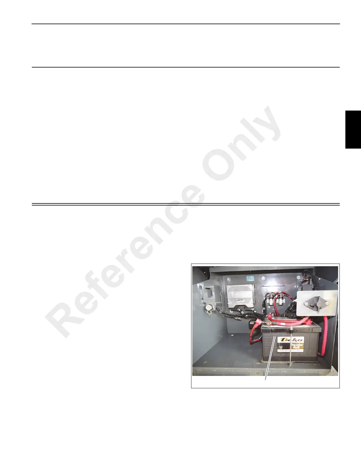
The batteries are located in a box on the left side of the crane
(1) (Figure 3-1). The batteries are the maintenance free type
and completely sealed except for a small vent hole in the
side. The vent hole allows what small amount of gases that
are produced in the battery to escape. On some batteries, a
test indicator located on the top of the battery is used to
determine if the battery can be tested in case of a starting
problem.
There is a battery disconnect switch (1) (Figure 3-2) located
to the right on the battery box.
Reference Only
 Loading...


