ELECTRIC SYSTEM RT540E SERVICE MANUAL
3-8 Published 4-20-2015, Control # 502-01
Battery Replacement
Removal
1. Ensure that the key switch has been in the OFF position
for 2 minutes.
2. Turn the battery disconnect switch to the OFF position.
3. Remove the ECM power fuse.
4. Remove the negative battery cables.
5. Remove the positive battery cables.
6. Tag and disconnect leads from the battery terminals
starting with the positive terminals.
7. Remove the nuts and washers from the bracket hold
down rods. Remove the hold down bracket.
8. Remove the batteries.
Installation
1. Place the batteries in the battery box.
2. Install the hold down brackets so they can hold down the
batteries. Secure the brackets (and batteries) to the
bracket hold down rods with nuts and washers.
3. Connect leads to the battery terminals starting with the
negative terminals (Figure 3-5)
4. Install the ECM power fuse.
5. Close the battery box cover.
6. Turn the battery disconnect switch to ON.
7. Verify replacement batteries work by starting crane’s
engine and operating various crane components.
Relay Panel Component Replacement
Accessory Relay
1. Ensure that the key switch has been in the OFF position
for 2 minutes.
2. Turn the battery disconnect switch to the OFF position.
3. Remove the hardware securing the console front cover
and remove the cover.
4. Tag and disconnect the electrical leads from the suspect
relay.
5. Remove the hardware securing the suspect relay to the
relay panel assembly. Remove suspect relay.
6. Install replacement relay on relay panel and secure it
with attaching hardware.
7. Connect the electrical leads to the relay as tagged
during removal.
8. Position the console front cover on the console and
secure with the attaching hardware.
9. Connect the batteries.
10. Turn the battery disconnect switch to the ON position.
11. Verify proper installation by operating all components
involved with the replacement relay verifying they all
work.
Rocker Switch Replacement
Use the following procedures and refer to Figure 3-6 when
removing/installing a switch.
Removal
1. Ensure that the key switch has been in the OFF position
for 2 minutes.
2. Turn the battery disconnect switch to the OFF position.
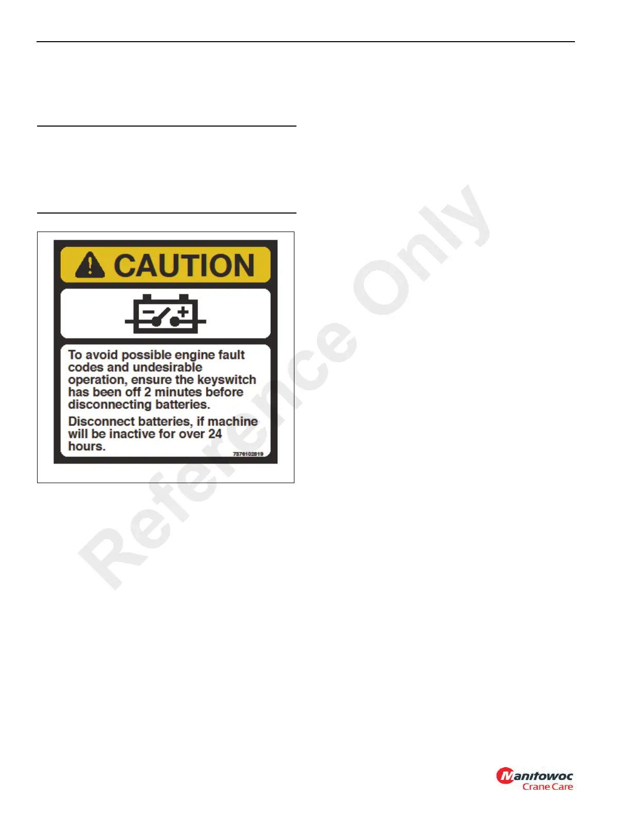
CAUTION
To avoid possible engine fault codes and undesirable
operation, ensure the keyswitch has been off 2 minutes
before disconnecting batteries.
Disconnect batteries, if machine will be inactive for over
24 hours.
Reference Only
 Loading...


