Published 4-20-2015, Control # 502-01 2-13
RT540E SERVICE MANUAL HYDRAULIC SYSTEM
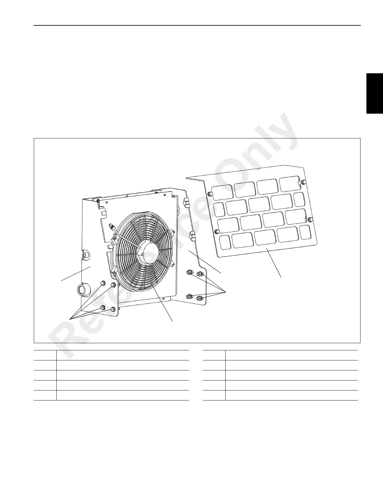
OIL COOLER
Description
An air cooled hydraulic oil cooler (Figure 2-5) is installed on
the rear of the superstructure behind the hoists.
When the oil temperature reaches 48.8°C (120°F), the
normally closed temperature switch opens to turn on the oil
cooler electric motor which drives the oil cooler fan.
The oil cooler fan pulls cool air through the cooling fins on the
cooler. Normally, most hydraulic oil from components is
routed through the oil cooler by way of a return line and on to
the filter in the reservoir. When several hydraulic functions
are being used at one time (i.e., hoisting, lifting, and
telescoping), more oil has to flow through this return line,
causing a pressure buildup. When this pressure reaches
206.8 kPa/2.0 bar (30 psi), the normally closed check valve
in the return line (in parallel with the return line through the
hydraulic oil cooler) will open, letting some hydraulic oil
bypass the hydraulic oil cooler and flow directly into the
reservoir filter.
When fewer functions are being used, the pressure in the
system will decrease below 206.8 kPa/2.0 bar (30 psi) and
the check valve will close again.
FIGURE 2-5
6
7
5
8
1, 2, 3, 4
1, 2, 3, 4
6770
Item Description
1 Flatwasher
2 Lockwasher
3 Capscrew
4Hex Nut
Item Description
5 Mounting Bracket
6 Mounting Bracket
7 Shield Plate
8 Oil Cooler
Reference Only
 Loading...


