GROVE Published 10-21-2010, Control# 198-04 8-1
5540F/YB5515 SERVICE MANUAL AXLES/DRIVE SHAFTS/WHEELS AND TIRES
SECTION 8
AXLES/DRIVE SHAFTS/WHEELS AND TIRES
DESCRIPTION
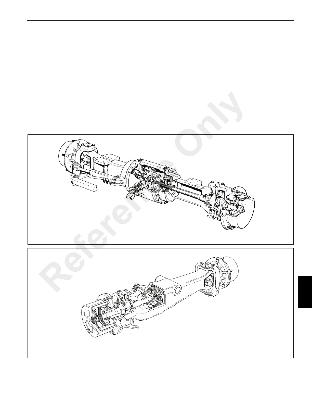
Front Axle
The front axle Figure 8-1 is a rigid-mounted drive axle,
attached to the frame of the crane by eight bolts, washers
and nuts. The axle includes a 3 piece spiral bevel input, two
reduction drive hubs and inboard brakes.
Rear Axle
The crane may be equipped with either a rear drive axle or
rear non-drive axle. Figure 8-2 shows only the drive axle.
The axle is pin mounted to the frame of crane, allowing it to
pivot in both directions. When the axle is equipped with axle
lockouts, the axle will pivot 4° in either direction when the
locks are not engaged. With oscillation locks engaged, the
axle will pivot 1-1/2° in both directions. On units with no axle
lockouts the axle will pivot 1-1/2° in both directions. The drive
axle includes spiral bevel input, two reduction drive hubs and
brakes in the drive hubs. The non-drive axle does not have a
3 piece spiral input.
FIGURE 8-1
F
Front Drive Axle
FIGURE 8-2
a0166
Rear Drive Axle
Reference Only
 Loading...


