11-29
5540F/YB5515 SERVICE MANUAL STRUCTURALS
MAIN WINCH (BRADEN MODEL)
Theory Of Operation
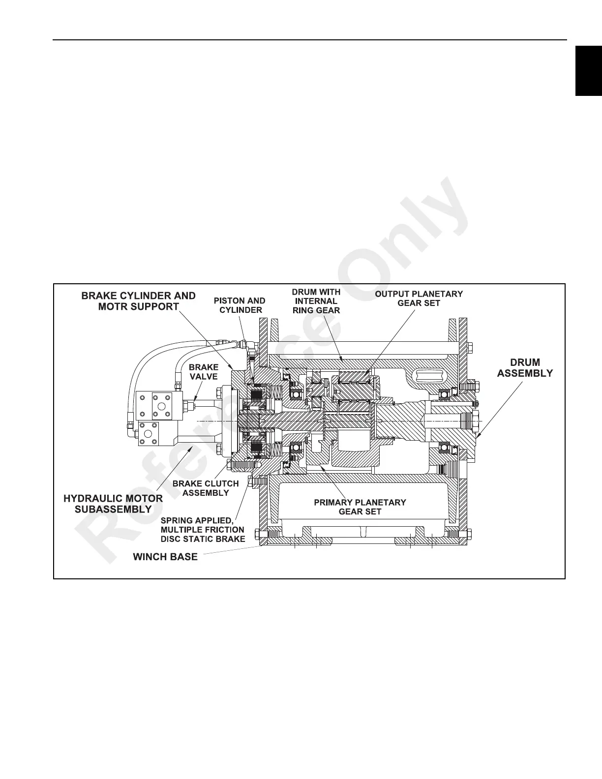
Description Of Winch (Figure 11-54)
The winch has five basic component parts:
1. Winch base.
2. Winch tension roller subassembly.
3. Hydraulic motor subassembly.
4. Brake cylinder and motor support.
5. Drum assembly.
The drum assembly consists of three assemblies:
1. 1.Drum with internal ring gear.
2. Output planetary gear set.
3. Primary planetary gear set.
The hydraulic motor is bolted to the motor support which in
turn is bolted to the brake cylinder and the base. The motor
end of the drum, rotating on a ball bearing, is supported by
the brake cylinder.The other end of the drum is rotates on a
ball bearing on the support bolted to the base. The ring gear
for both planetary sets is machined into the drum’s inside
surface.
Winch Operation
The hydraulic motor drives the sun gear of the primary
planetary gear set through the spline dinner race of the brake
clutch. When driven by the sun gear, the primary planet
gears walk around the ring gear in the drum and drive the
planetary carrier.
The primary planet carrier drives the output planet sun gear,
which in turn drives the planet gears.The output planet
carrier is splined to the bearing support and cannot rotate.
Therefore, as the output planet gears are driven by the sun
gear, they will drive the ring gear/drum.
Dual Brake System -Description
The dual brake system consists of dynamic brake system
and a static brake system.
The dynamic brake system has two operating components:
1. Brake valve assembly.
2. Hydraulic motor.
The brake valve is a counterbalance valve which contains a
check valve to allow free flow of oil to the motor in the
hoisting direction, and a pilo operated, spring loaded spool
valve that blocks the flow of oil out of the motor when the
control valve is placed in neutral.
When the main control valve is placed in hoisting position,
FIGURE 11-54
a2205
Winch Cut-Away View
Reference Only
 Loading...


