GROVE Published 10-21-2010, Control# 198-04 10-5
5540F/YB5515 SERVICE MANUAL STEERING SYSTEM
When moving side ways to the right Figure 10-3, hydraulic oil
under pressure from the steering pump flows to the steering
orbitrol in the operator’s compartment. When the steering
wheel is turned to the right, hydraulic fluid is directed through
port R of the steering orbitrol to port C2 of the rear steering
solenoid valve. The rear steering solenoid valve is energized
in crab steer mode, therefore the hydraulic oil flows out Port
V2 to the rod end of the right rear steering cylinder and the
base end of the left rear steering cylinder. The right cylinder
rod retracts and the left cylinder rod extends, turning the rear
wheels to the right. Oil under reduced pressure from the rear
steering cylinders flows back through Ports V2 and C1 of the
rear steering solenoid valve to Ports C2 of the front steering
solenoid valve. In crab steer mode, the front steering
solenoid valve is actuated and oil flows through Ports C2 and
V2 to the rod end of the left front steering cylinder and the
base end of the right front steering cylinder. The left front
cylinder rod retracts while the right front cylinder rod extends,
turning the wheels to the right. Return oil from the steering
cylinders flows back to tank through Ports V1 and C1 of the
front steering solenoid valve and Ports L and OUT of the
steering orbitrol.
RELIEF VALVE PRESSURE CHECK AND
ADJUSTMENT
Pressure Check
1. Remove the deck cover over the hydraulic valves by
removing four socket head screws.
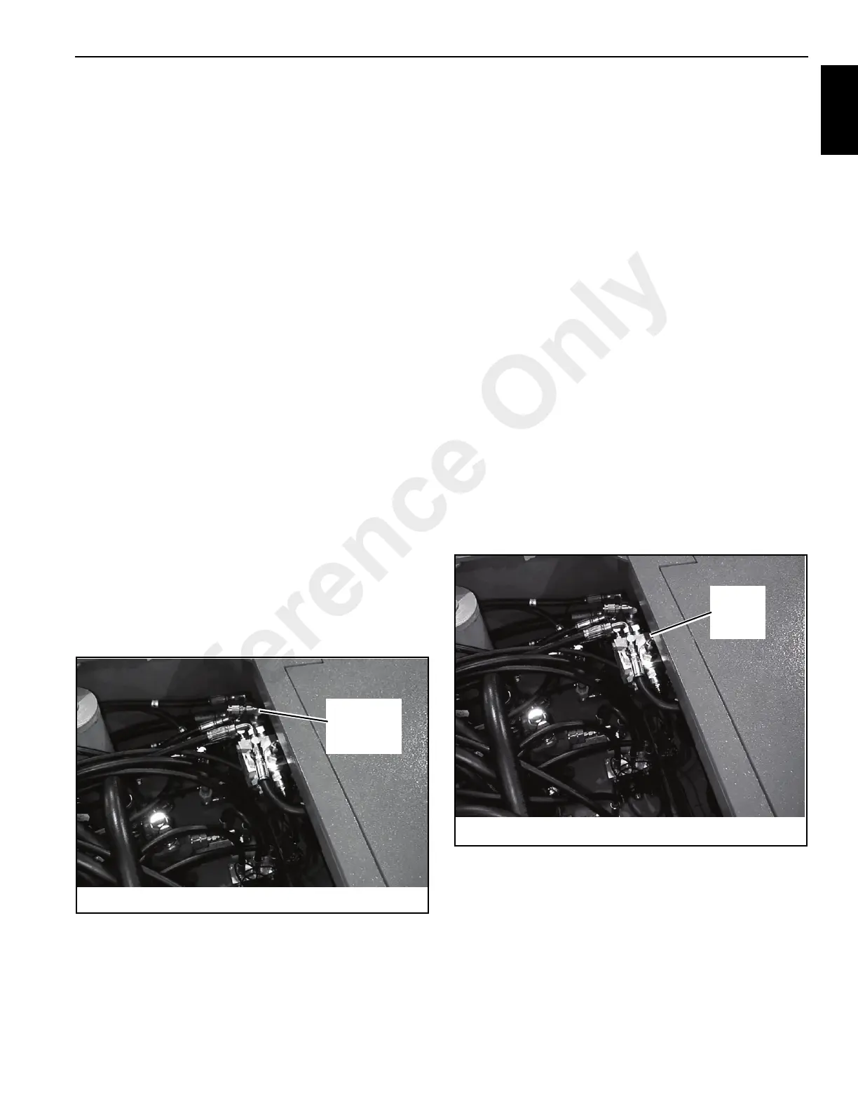
2. Remove the cap Figure 10-4 from the quick-disconnect
fitting located in the return circuit from the relief valve.
Connect a 0-3000 psi (20 670 kPa) pressure gauge to
the quick-disconnect fitting.
3. Start the engine allowing the hydraulic oil to reach
operating temperature. Increase the engine speed to full
rpm. Turn the steering wheel and put the wheels at the
maximum angle. Continue to turn the steering wheel
after the wheels are at their maximum angle. Read the
pressure gauge and then release the steering wheel.
4. The correct pressure reading is 2500 ± 50 psi (17 225 ±
345 kPa). If not correct adjust the relief valve pressure
setting.
Pressure Adjustment
1. Loosen the jam nut Figure 10-5 on the relief valve.
2. Start the engine. Turn the steering wheel and put the
wheels at the maximum angle. Continue to turn the
steering wheel after the wheels are at their maximum
angle. Read the pressure gauge.
3. While holding the steering wheel and turn the adjusting
screw clockwise (IN) to increase the pressure and
counterclockwise (OUT) to decrease the pressure.
4. When correct setting is obtained, release the steering
wheel and tighten the jam nut on the relief valve.
5. Recheck the pressure setting and adjust if necessary.
6. Remove the pressure gauge and install the cap.
7. Install the deck cover.
FIGURE 10-4
p0708
Steering Relief
Pressure
Check Point
FIGURE 10-5
p0711
Steering
Relief
Valve
Reference Only
 Loading...


