GROVE Published 10-21-2010, Control# 198-04 9-9
5540F/YB5515 SERVICE MANUAL
c. Using a suitable pen, mark the level line (C) of the
fluid in the tube.
d. After approximately 1/2 hour, check if the level has
dropped below the original marked line. If it has then
check the brake piston seals for slight nicks, cuts or
general wear.
6. Repeat steps 3 through 5 for the opposite brake piston
seals.
7. Reconnect all brake lines and bleed the brake system as
recommended on page 9-5.
SERVICE BRAKE REPAIR
Front Axle Brakes
NOTE: It is recommended that the axle be removed from
the machine when disassembling the front axle
brakes. See Servicing the Front Axle in Section 6.
Disassembly
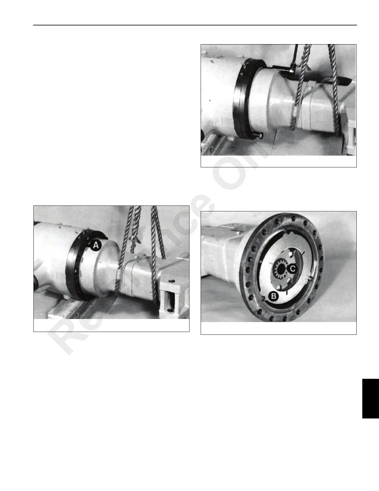
1. Support the axle arm Figure 9-14 and remove bolts A.
2. Jack the axle arm off the drive head, using drive head
securing bolts Figure 9-15. Remove all traces of gasket
from the mating surfaces.
3. There are two counterplates B Figure 9-16 one at each
end of the brake pack, which are secured to the plate
carrier B. If the plates are to be reused, note their
position and which way round they are then remove the
brake pack.
4. Remove the retaining ring Figure 9-17. If the brake pack
is to be reused, note the position of the plates before
removing them.
NOTE: The planet carrier has an internal chamber at the
end which faces away from the drive head.
Reference Only
 Loading...


