GROVE Published 10-21-2010, Control# 198-04 4-13
5540F/YB5515 SERVICE MANUAL HYDRAULIC SYSTEM
Main Control Valve
Technical Data
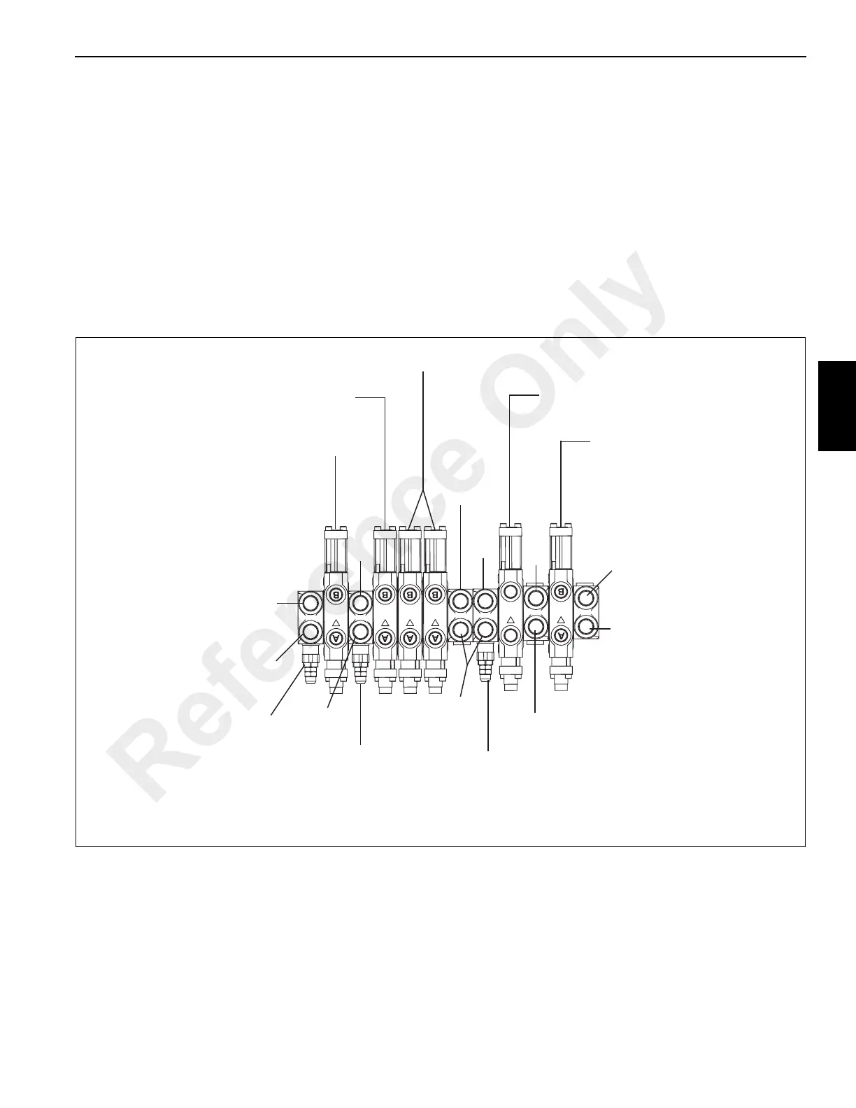
Valve Identification
Valve Description
The main control valve bank consists of one single valve
assembly, Figure 10-9. The valve assembly if mounted in the
front of the cab on the dash. The control valve is a multi-
section, open-center, three position, four-way directional
control valve equipped with self-centering valve spools.
The control valve consists five inlet sections with three relief
valves, one outlet section, and four or six parallel working
sections and two single working sections. The swing and
outrigger working sections are a cylinder spool section and
all others are motor spool sections.
Motor spool sections allow oil to return to the hydraulic tank
when the valve spool in the centered or neutral position.
Cylinder spool sections block the oil from returning to the
hydraulic tank when the valve spool is in the centered or
neutral position.
Spool type Sliding, double action, cylinder
Hoist, Crowd and Lift Circuits and outriggers Main Relief Valves See Figure 4-9
Swing Circuit Main Relief Valve See Figure 4-9
Spool travel (from neutral) 5/16 inch (7,87 mm)
Port pressurized (3-Spool Control Valve):
Handle In - Spool out A-Port
Handle out - Spool in B-Port
T1
Outlet
P1
Inlet
A= Swing Right
B= Swing Left
Cylinder
Spool
P2
Inlet
Motor Spool
A= (Tele) Boom In
B= (Tele) Boom Out
Cylinder Spool
A= Outrigger Down
B= Outrigger Up
Power
Beyond
P3
Inlet
Motor Spool
A= Hoist Up
B= Hoist Down
Motor Spool
A= (Left) Boom Down
B= (Left) Boom Up
P4
Inlet
T2
Outlet
Plugged
Port
Plugged
Port
Winch Main
Relief Valve
3500 psi (24, 132 kpa)
Plugged
Port
Croud Lift
Outrigger Main
Relief Valve
3500 psi (24, 132 kpa)
Plugged
Port
Swing Main
Relief Valve
2000 psi (13, 740 kpa)
FIGURE 4-9
a1565
Main Control Valve Identification
Reference Only
 Loading...


