GROVE Published 10-21-2010, Control# 198-04 9-19
5540F/YB5515 SERVICE MANUAL
TROUBLESHOOTING
Service Brakes
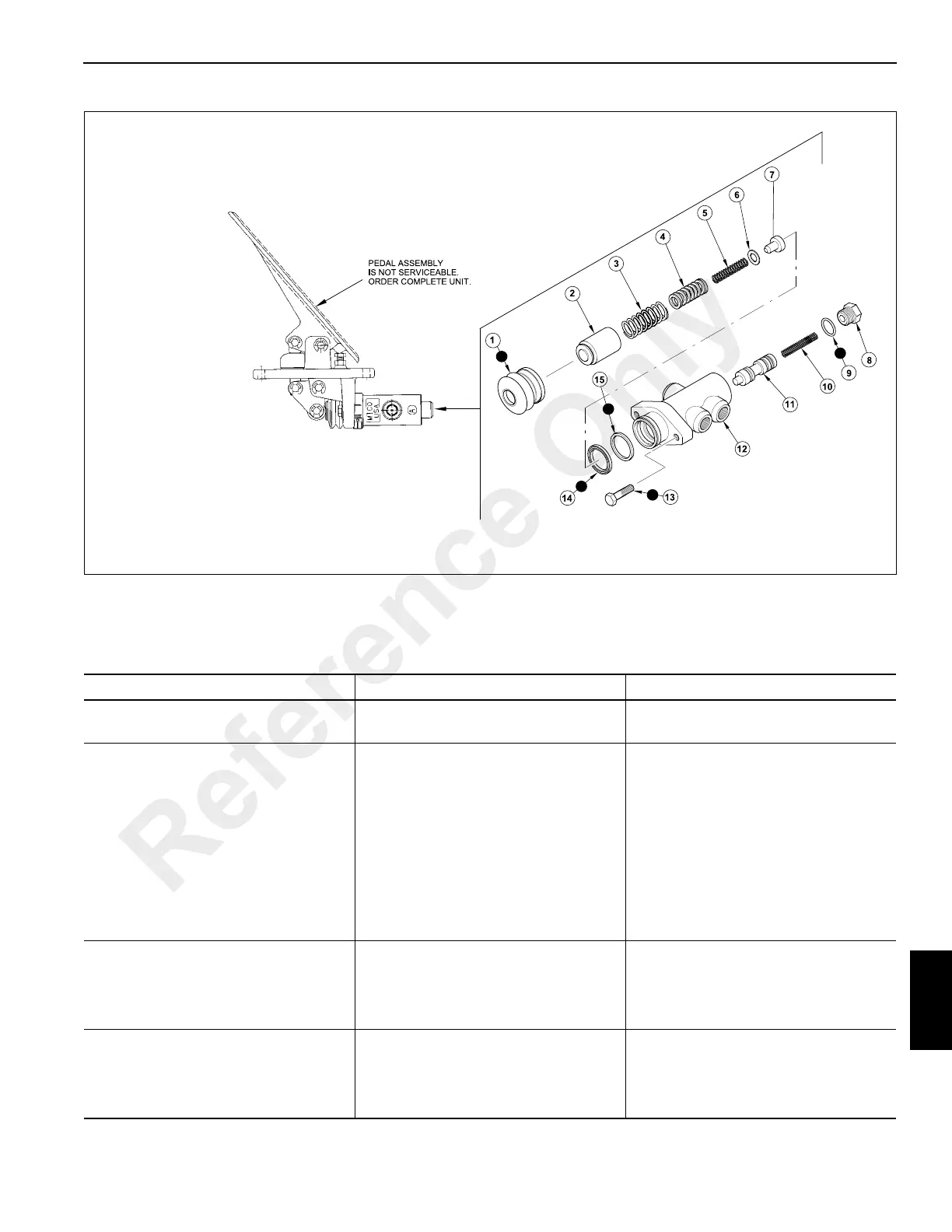
FIGURE 9-31
a0780
1. Boot
2. Piston Assembly
3. Spring
4. Spring
5. Spring
6. Shim
7. Retainer Assembly
8. End Plug
9. O-ring
10. Spring
11. Spool
12. Housing
13. Screw
14. Cup
15. Seal
Brake Modulating Valve
PROBLEM POSSIBLE CAUSE REMEDY
Warning light on instrument panel
illuminates.
1. Loss of brake pressure. 1. Any cause under NO BRAKES.
No brakes. 1. Faulty brake modulating valve.
2. Faulty priority flow control valve.
3. Loss of fluid from broken line,
loose fitting of hose.
4. Leakage past both brake pistons.
5. Faulty pump section.
6. Faulty accumulator charging
valve.
1. Repair or replace.
2. Replace.
3. Check all circuit lines, hoses and
fittings. Tighten or replace.
4. Perform leakage test.
5. Replace pump.
6. Replace valve.
Bad brakes (pedal fully applied, crane
gradually stops).
1. Severe wear in service brake
discs.
2. Leakage past one brake piston.
1. Replace brake discs. See Section
6.
2. Perform leakage test. Repair or
replace. See Section 7.
Soft brake pedal. 1. Air in system.
2. High pressure leaks - external.
1. Bleed brake system.
2. Apply full brake pressure, inspect
for leakage in lines, hoses and
fittings.
Reference Only
 Loading...


