GROVE Published 10-21-2010, Control# 198-04 7-3
5540F/YB5515 SERVICE MANUAL TRANSMISSION AND TORQUE CONVERTER
DESCRIPTION OF OPERATION
General
The transmission consists of a torque converter, hydraulic
reverser unit and integral manual four speed gearbox.
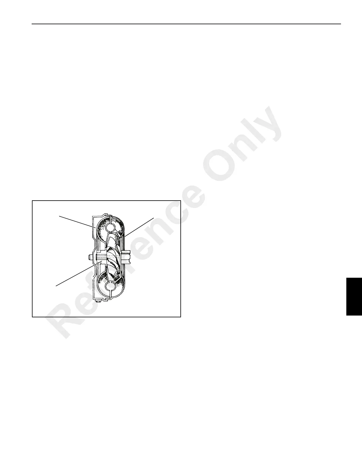
Torque Converter
The torque converter is the hydraulic link between the engine
and the drive train. There are three main components in the
torque converter:
1. A turbine
2. An impeller (pump)
3. A stator and One-Way Clutch
The impeller is the pump for the torque converter. This
component starts the movement of the oil to the other
components. The impeller is connected to the engine
flywheel through the torque converter and a drive plate. The
impeller rotates at engine speed. Similar to a centrifugal
pump, the impeller takes oil at the inner diameter and
releases the oil at the outer diameter.
The turbine is opposite the impeller and is connected by
splines to the input shaft of the transmission. The turbine
receives oil at the outer diameter and releases the oil to the
stator at the inner diameter. The movement of oil from the
impeller to the turbine makes a multiplication of torque
possible. The torque converter gives maximum torque when
the turbine is at zero (0) rpm.
The stator is between and at the center of the impeller and
turbine. The stator changes the direction of the oil which
leaves the turbine so the oil will enter correctly again into the
impeller.
The torque converter and transmission have a common
hydraulic system. Figure 7-2 and Figure 7-3 shows the
arrangement of the system.
NOTE: Normal operating temperature is 180° - 190° F (82°
- 88° C). High temperatures will cause damage and
leakage in the seals and gaskets of the torque
converter. Do not continue operation if the
temperature increases above 180° - 190° F (82° -
88° C). A warning light on the cab instrument panel
will illuminate when the temperature rises above a
safe temperature. Put the transmission in “neutral”
position and let the engine run at low rpm until the
temperature returns to normal and the warning light
goes out. If temperature does not return to normal,
check for restriction in the lubrication and cooling
lines of the torque converter.
Transmission
The reverser unit A has a pair of hydraulically operated
clutches giving forward - neutral - reverse drive. Oil pressure
is provided by a crescent type pump B driven at engine
speed by the drive lugs of the torque converter C. The oil
passage is controlled by the pressure maintaining valve D,
and clutch selection is achieved by means of an electric
solenoid valve E.
Drive is transferred from the reverser unit by helical gears to
the mainshaft F, which carries the 3rd/4th synchromesh unit
G, and to the layshaft H, which carries the 1st/2nd
synchromesh unit J. The synchromesh units are of the
“Blocking Pin” type. See description of the Synchromesh
Unit, page 7-7.
Drive is transmitted finally via the output shaft K to the rear
axle. If 4 wheel drive is selected, the front wheels are also
driven via 4 wheel drive output yoke L. A full description of 2/
4-wheel drive clutch operation is given in Hydraulic 2/4-
Wheel Drive Unit Operation.
Driveshaft T is permanently driven by the engine and runs
through the hollow forward/reverse unit shaft to the back of
the gearbox. The shaft T drives a gearbox mounted main
hydraulic pump (if fitted).
Oil is drawn from the gearbox sump via strainer P by pump
B. Pressurised oil from the pump is fed through an internal
passage via the filter Q to the pressure maintaining valve D,
which maintains pressure to the solenoid valve E for forward/
reverse clutch selection. Excess oil from the maintaining
valve flows back through casing cross drillings to the torque
converter S. Oil enters the converter between the converter
hub and the stator support, and leaves between the stator
and the input shaft. Pressure in the converter is controlled by
a regulating valve C which dumps excess oil from the
converter line back to the sump.
Torque converter relief valve V acts as a safety valve should
the system pressure suddenly rise above normal, protecting
the torque converter from being damaged.
Oil from the torque converter flows out of the transmission to
the external oil cooler Z, returning at the rear of the
FIGURE 7-1
a2030
Turbine
Stator
Input Output
Impeller
Reference Only
 Loading...


