GROVE Published 10-21-2010, Control# 198-04 7-7
5540F/YB5515 SERVICE MANUAL TRANSMISSION AND TORQUE CONVERTER
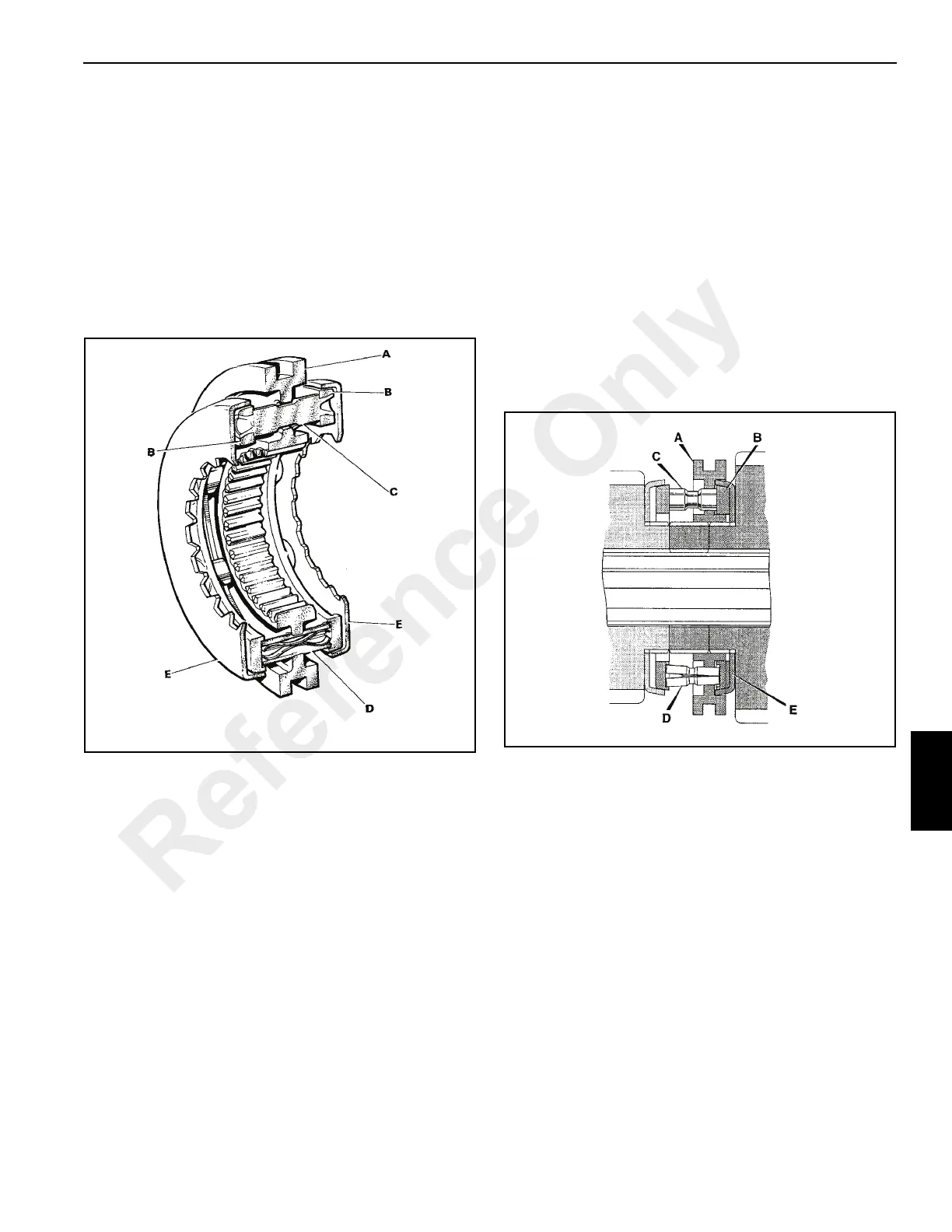
Synchromesh Unit
Description
The transmission is equipped with “Blocking Pin”
synchromesh units, comprising of the following parts:
a. SYNCHRO HUB (A). Controls the operation of the
synchromesh unit and gear selection, the selector
fork engaging into the outer groove. Internal dog
teeth link the selected gear to the drive shaft.
Through the synchro hub center are two sets of
holes for the blocker pins (C) and the split energizer
pins (D), spaced alternately.
b. SYNCHRO RINGS (B). They are rigidly joined by
the blocker pins, with the split energizer pins held, in
counterbores, between the two synchro rings.
c. BLOCKER PINS (C). These pins have a narrow
neck in the center, against which the synchro hub
transmits radial drive during gear changes. The
edges of the blocker pin neck and their mating
synchro hub holes are designed so that, as the
radial loads are reduced, the synchro hub can slide
over the shoulder of the blocker pin.
d. SPLIT ENERGIZER PINS (D). These pins take the
initial axial load of the synchro hub on the shoulder
of the split energizer pin neck. As the axial load
reaches approximately 90 lb. (40.8 kg) the internal
springs allow the split energizer pin to collapse and
the synchro hub to move axially.
e. SYNCHRO CUPS (E). These take the frictional
drive from the synchro ring on their inner faces. The
synchro cups are splined to drive their respective
gears while synchronization is taking place.
Operation
Figure 7-5 shows the gearbox with the first gear engaged.
Synchro ring B is in contact with synchro cup E and the
synchro hub dog teeth are linking first gear to the shaft gear.
In this position the split energizer pins D are “collapsed.”
When selecting second gear the synchro hub A slides along
the split energizer pins until the pin recess and synchro hub
flange are in line. At this point, the split energizer pins open
and the synchro rings are moved by the synchro hub pushing
on the split energizer pin shoulder.
Initial contact between the synchro ring and the synchro cup
starts to synchronize the speed of the shaft and second gear.
The rotational force of the synchro ring is taken by the
blocker pin against the edge of the synchro hub hole as
shown in Figure 7-6.
Reference Only
 Loading...


