5540F/YB5515 SERVICE MANUAL
9-2 Published 10-21-2010, Control# 198-04
DESCRIPTION
There are two brake systems used on the crane; the service
brake system and the parking brake system.
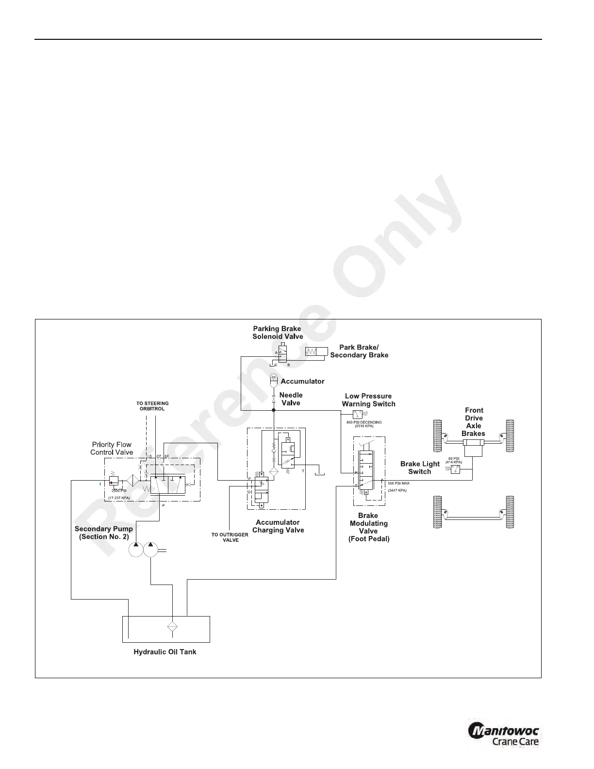
Service Brake System
The service brake system Figure 9-1 and Figure 9-2 consists
of the second section of the secondary hydraulic pump, a
relief valve included in the priority flow control valve, an
accumulator charging valve, a low pressure warning switch,
an accumulator, a needle valve, a brake modulating valve, a
brake light switch and the front and rear axle service brakes.
Description Of Operation
Hydraulic Pump
The secondary hydraulic pump (Section No. 2) supplies
hydraulic oil flow to the priority flow control valve Figure 9-1.
Priority Flow Control Valve
The priority flow control valve in normal operation supplies oil
to the accumulator charging valve. If oil is required for the
steering operation the priority flow control valve shifts to
furnish flow to the steering system. (See Steering System,
Section 8) The priority flow control valve also includes the
relief valve used to protect the steering and brake systems.
Accumulator Charging Valve
The accumulator charging valve supplies oil to the
accumulator on demand. This is accomplished at a preset
rate at a selected pressure; neither of which is adjustable.
The flow to the downstream brake modulating valve will be
reduced fractionally for a short time when the accumulator is
charging. This does not noticeably affect the operation of
these components. Full system pressure is available to the
downstream components at all times, providing oil delivery
and pressure from the pump and relief valve are not
impeded.
The accumulator charging flow rates and upper and lower
pressure limits are set at the time of manufacture and are not
adjustable.
Reference Only
 Loading...


