11-61
5540F/YB5515 SERVICE MANUAL STRUCTURALS
Assembly
1. If removed, install bushing 2 and 4 into worm housing 1
and worm housing cover 3.
2. Install bearing cups 8 and bearing cones 9 onto worm
shaft 7.
3. Install the assembled worm shaft and bearings into
worm housing 1. Seat the bearing cones into the worm
housing.
4. Install a new oil seal 16 into worn housing 1.
5. Insert output pinion shaft 7 through oil seal 16and
bushing 2.
6. Install the lower retainer ring 12 over the output pinion
shaft.
7. Install worm gear 5 onto output gear shaft 7. Mesh the
teeth of the worm gear with the teeth of the worm.
8. Install retaining ring 14. Install the top retaining ring 12.
9. Place a new 0.031” thick gasket 19 on bearing retainer
10.
10. Attach the gasket and bearing retainer to the worm
housing using four lockwashers 27 and capscrews 23.
11. Place a new 0.015” thick gasket 17 and shim 22 on the
motor adapter 11.
12. Using four socket head capscrews 21 and lockwashers
25 attach motor adapter to 11 to worm housing 1.
13. Check the backlash between the worm and worm gear
in both directions. Backlash should be 0.010” (0.254
mm) or less.
14. Place a new worm cover gasket 20 on the face of worm
housing 1. Using six capscrews24 and lockwashers 26,
attach worm housing cover 3 to the worm housing. Coat
the threads of capscrews 23 with Loctite No. 242 before
installation.
15. Check the end play on the worm shaft using a dial
indicator. Set the base of dial indicator on the worm gear
housing. Turn the output gear in one direction slightly.
Place the dial indicator on the end of the worm shaft and
set it to zero (0). Turn the output gear in the opposite
direction and read the dial indicator. The end play must
be between 0.000 to 0.002 inches (0.000 to 0.05 mm).
Add or remove shims as necessary to obtain the correct
end play.
16. Fill the gear housing with the recommended gear
lubricant. See Section 3.
17. Using a new gasket, install the hydraulic motor 13 to
motor adapter 11 using capscrews 28 and lockwashers
25.
Installation
1. Install the gearbox in reverse order of removal.
2. Align the pinion gear with the swing gear following the
instructions.
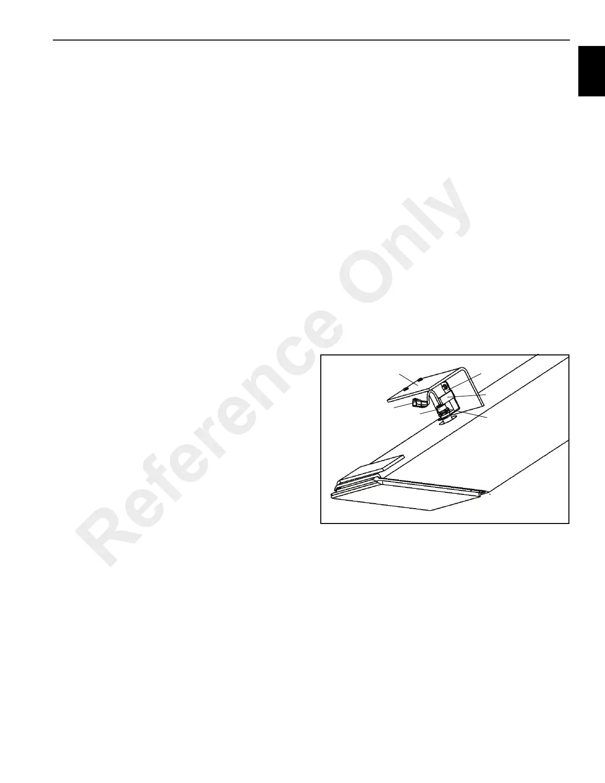
OUTRIGGERS
Outrigger Monitoring System
(OMS)(Optional—Standard in North
America)
The Outrigger Monitoring System (OMS) proximity switches
(if equipped) are mounted outside the outrigger housing
tubes. The proximity switches identify whether an outrigger
beam is at the fully extended position or at any position less
than fully extended.
Removal
1. Disconnect switch cable (1) from harness.
2. Remove switch mounting bracket (2).
3. Remove jam nuts (3) and thread switch (4) out of the
mounting bracket.
Installation
1. Feed cable through the mounting bracket and jam nuts.
2. Thread switch through mounting bracket.
3. Thread nuts on switch.
4. Thread switch up until it touches tab (5) of mounting
bracket and LED is pointed away from the bracket.
5. Tighten jam nuts against mounting bracket.
6. Install bracket with switch onto outrigger angle bracket
(6).
7. Adjust bracket and/or switch to have .12 to .38 in (3 to 10
mm) gap beween end of switch and outrigger beam.
8. Connect switch cable to wire harness.
Reference Only
 Loading...


