STEERING SYSTEM 5540F/YB5515 SERVICE MANUAL
10-24 Published 10-21-2010, Control# 198-04
STEERING CYLINDER
Technical Data
Cylinder Bore. . . . . . . . . . . . . . . . . . . . . . . . . . . . . . . . . . . . .2.36 inches (60 mm)
Stroke . . . . . . . . . . . . . . . . . . . . . . . . . . . . . . . . . . . . . . . . . ..8.30 inches (211 mm)
Rod Diameter. . . . . . . . . . . . . . . . . . . . . . . . . . . . . . . . . . . . .1.18 inches (30 mm)
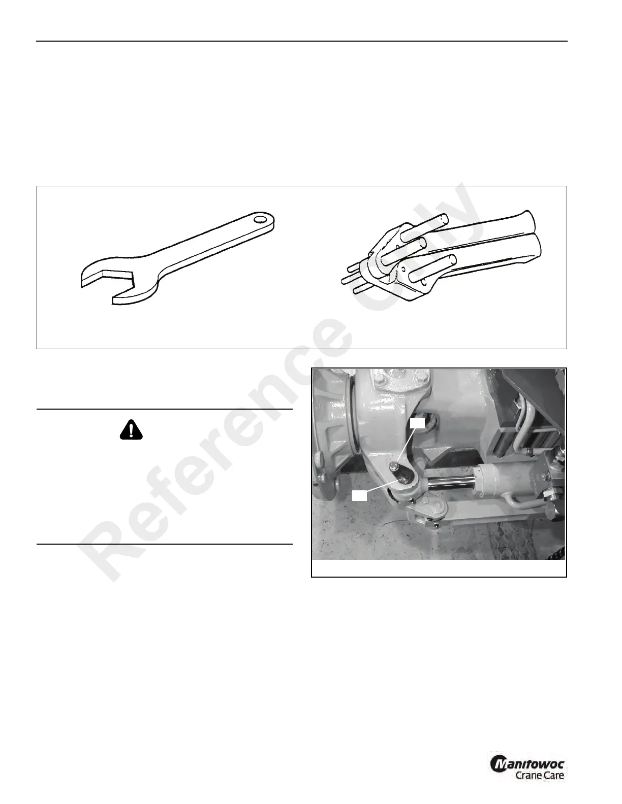
Special Tools
Cylinder Repair
Removal
1. Raise and support the machine to gain access to the
steering cylinder.
2. With the engine not running, turn the steering wheel in
both directions to release any pressure in the hydraulic
lines to the steering cylinder.
3. Be prepared to collect the oil as you remove the steering
lines. Slowly loosen the hydraulic hoses to release any
remaining pressure. Install a plug in the hose end and a
cap on the cylinder port. Place a tag on the hoses for
identification and correct assembly.
4. Remove locking bolts A Figure 10-31 and pivot pins B
from both ends of the steering cylinder.
5. Remove the steering cylinder from the axle.
Disassembly
1. Remove the caps from the cylinder ports and drain
remaining oil from the cylinder.
2. Secure the cylinder. If a vice is used, clamp only on the
base end of the cylinder, DO NOT clamp across the
cylinder tube.
3. Loosen end cap 13 Figure 10-32 using a special
spanner wrench (See Special Tools, Figure 10-30) and
remove the piston rod assembly 16 from the cylinder
barrel.
FIGURE 10-30
a0340 a0341
Hexagon Spanners for Cylinder
Pistons and End Caps
Hexagon Spanners for Cylinder
Pistons and End Caps
Gland Seal Fitting Tool
WARNING
A raised and badly supported machine can fall on you
causing severe injury or death. Position the machine on a
firm, level surface before raising one end. Ensure that the
other end is securely chocked. Do not rely solely on the
machine hydraulics or outriggers to support the machine
when working under it.
Disconnect the battery cables while you are under the
machine, to prevent the engine from being started.
Reference Only
 Loading...


