HYDRAULIC SYSTEM 5540F/YB5515 SERVICE MANUAL
4-18 Published 10-21-2010, Control# 198-04
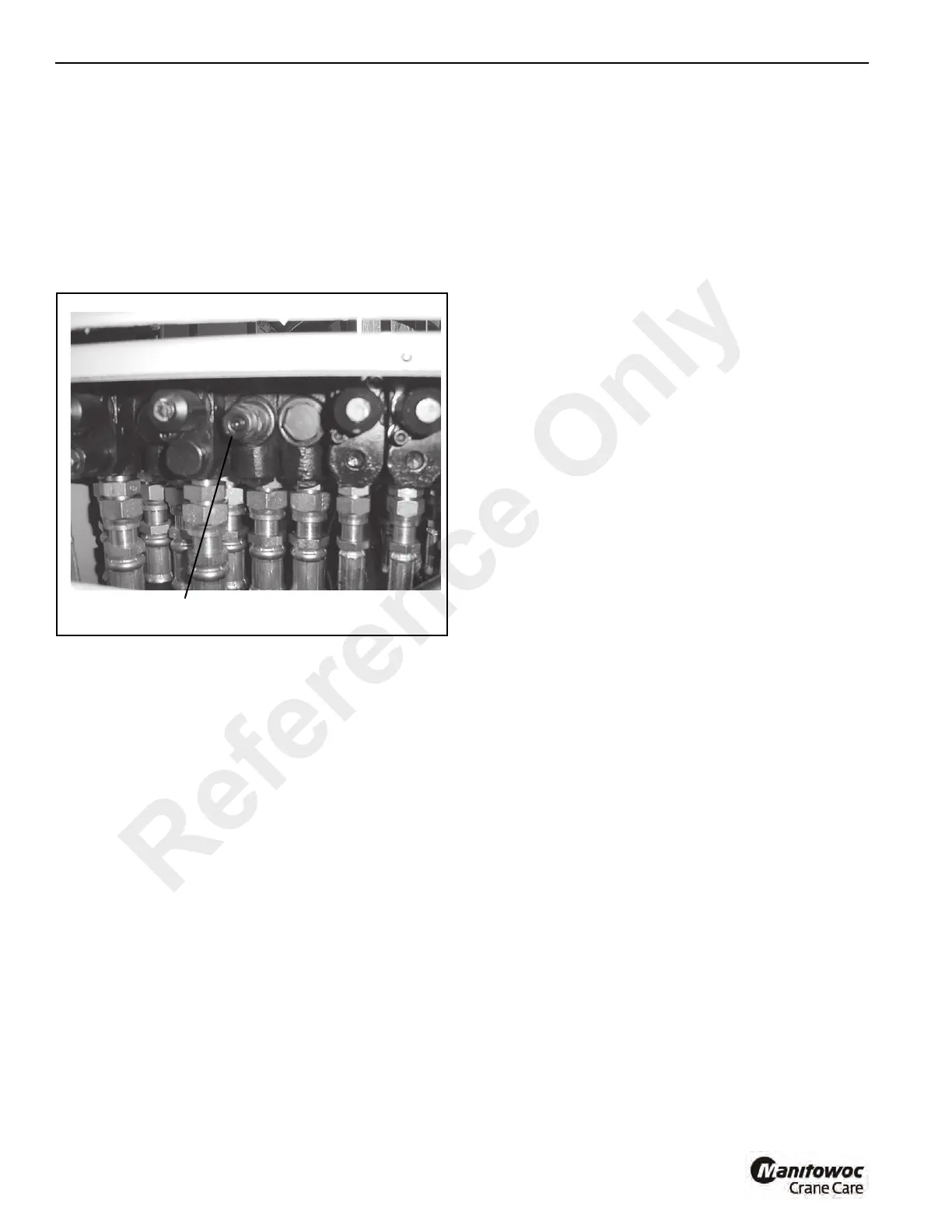
Winch Hoist/Circuit Main Relief Valve Adjusting
Procedure
1. With the engine shut off and the parking brake engaged,
connect a 0 - 5000 psi (0 - 345 bar) to the test
connection on the pressure side of the winch hoist
section of the hydraulic pump (Figure 4-15).
2. Remove the access panel in front of the cab control
panel to gain access to the main control valve
(Figure 4-20).
3. Loosen the jam nut on the winch hoist/boom lift main
relief valve (Figure 4-20).
4. Disconnect the hoist brake line between the hoist brake
valve and hoist brake. Cap and plug all openings.
5. Start the engine and accelerate it full rpm.
6. Actuate the winch hoist control to raise the cable
assembly Hold the control in position and observe the
pressure gauge attached to the pump outlet.
7. Turn the relief valve adjusting screw until a pressure
reading of 3500 ± 50 psi (241 ± 3.5 bar) is obtained.
Turning the adjusting screw clockwise will increase the
pressure; turning the adjusting screw counterclockwise
will decrease the pressure.
8. Release the control lever. Tighten the jam nut on the
relief valve. Actuate the lever again and check the
pressure reading. If correct stop the engine and remove
the pressure gauge. If incorrect, readjust the pressure
setting until correct.
9. Reconnect the hoist brake line.
LIFT CIRCUIT
General
The lift hydraulic circuit (Figures 10-21 through 10-23)
includes the lift cylinders, two holding valves, Ports 3 and 4 in
the hydraulic swivel, an anti-double block cutout solenoid
valve, the valve section of the control valve, and the
hydraulic lines.
Oil Flow
When the valve spool is in the neutral position, both A and B
ports are closed and oil is held in the circuit to inhibit
movement of the lift cylinders.
Raising the Booms
Pulling the handle spool IN connects the supply from the
pump to part B in the control valve (Figure 4-21). Oil leaves
Port B of the control valve section and passes through Port 3
of the hydraulic swivel and enters the base end of the lift
cylinder through the holding valve. In this direction, the oil
flows freely through the holding valve and into the base end
of the cylinder. The cylinder rod starts to extend, pushing oil
ahead of the piston out the rod end port. The oil returns
through Port 4 of the hydraulic swivel to Port A of the control
valve section. From here, the oil is routed to the tank
passage of the control valve assembly and returns through
the return filter to the hydraulic oil tank.
The anti-double block valve will shut off the oil supply to the
cylinder in the event the hook block comes in contact with the
boom head. In this case, the operator must let out more rope
on the main winch before the boom can be raised.
Lowering the Booms
Pushing the handle spool OUT sends oil in the opposite
direction and causes the cylinder to retract Figure 4-22. The
holding valve lets the cylinder retract only if there is oil under
pressure available to the rod port of the cylinder. See Holding
Valve.
a1648
Winch Hoist Main Relief Valve Location
FIGURE 4-20
Reference Only
 Loading...


