GROVE Published 10-21-2010, Control# 198-04 4-17
5540F/YB5515 SERVICE MANUAL HYDRAULIC SYSTEM
Swing Circuit Main Relief Valve Adjusting Procedure
1. With the engine shut off and parking brake engaged,
install a 0 - 5000 psi (0 - 345 bar) pressure gauge to the
test connection on the pressure side of the swing section
of the hydraulic pump (Figure 4-14).
2. Disconnect both hoses at the swing motor. Plug the
hoses and cap the fittings on the motor.
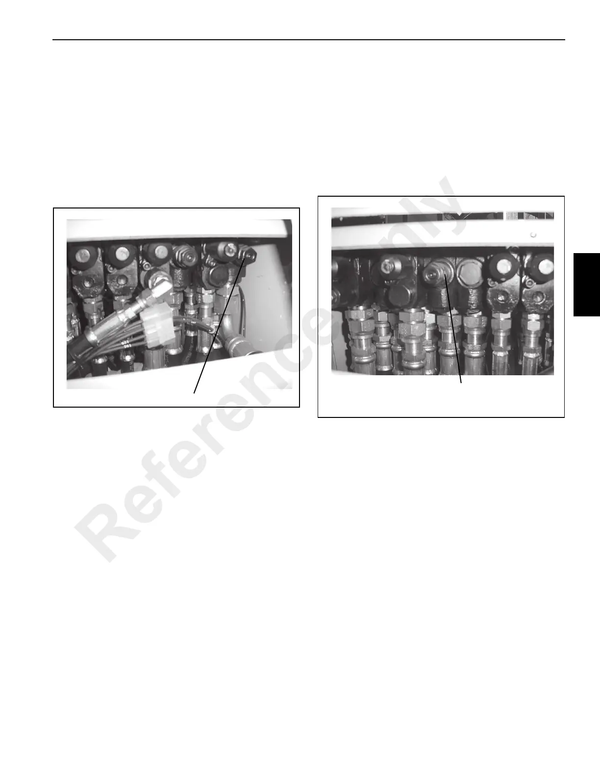
3. Remove the access panel in front of the cab control
panel to gain access to the main control valve
(Figure 4-18).
4. Loosen the jam nut on the swing main relief valve
(Figure 4-18).
5. Start the engine and accelerate it full rpm.
6. Actuate the swing control and observe the pressure
gauge attached to the pump outlet.
7. Turn the relief valve adjusting screw until a pressure
reading of 2000 ± 50 psi (138 ± 3.5 bar) is obtained.
Turning the adjusting screw clockwise will increase the
pressure; turning the adjusting screw counterclockwise
will decrease the pressure.
8. Release the control lever. Tighten the jam nut on the
relief valve. Actuate the lever again and check the
pressure reading. If correct stop the engine and remove
the pressure gauge. If incorrect, readjust the pressure
setting until correct.
9. Remove the plugs and caps and connect the hoses to
the swing motor.
Boom Lift/Telescope/Outrigger Circuit Main Relief
Valve Adjusting Procedure
1. With the engine shut off and the parking brake engaged,
connect a 0 - 5000 psi (0 - 345 bar) to the test
connection on the pressure side of the boom lift/
telescope/outrigger section of the hydraulic pump
(Figure 4-15).
2. Remove the access panel in front of the cab control
panel to gain access to the main control valve
(Figure 4-19).
3. Loosen the jam nut on the telescope/outrigger main
relief valve (Figure 4-19).
4. Start the engine and accelerate it full rpm.
5. Actuate the boom lift control to fully lower the boom.
Hold the control in this position and observe the
pressure gauge attached to the pump outlet.
6. Turn the relief valve adjusting screw until a pressure
reading of 3500 ± 50 psi (241 ± 3.5 bar) is obtained.
Turning the adjusting screw clockwise will increase the
pressure; turning the adjusting screw counterclockwise
will decrease the pressure.
7. Release the control lever. Tighten the jam nut on the
relief valve. Actuate the lever again and check the
pressure reading. If correct stop the engine and remove
the pressure gauge. If incorrect, readjust the pressure
setting until correct.
p1647
Swing Main Relief Valve Location
FIGURE 4-18
Boom Lift/Telescope/Outrigger Main relief Valve
Location
FIGURE 4-19
p1647
Reference Only
 Loading...


