HYDRAULIC SYSTEM 5540F/YB5515 SERVICE MANUAL
4-14 Published 10-21-2010, Control# 198-04
Parallel Valve Spool Description
A parallel spool is a solid-core spool designed to route oil
from the work circuit back to tank.
In a valve assembly that has all parallel valve spools, if two
are shifted at the same time, the spool closest to the valve
inlet will block the open-center passage and prevent supply
oil from reaching the other spools downstream. If the first
spool is shifted to only partially block the center passage, the
oil will enter the work circuit which offers the least resistance.
Oil always flows the path of least resistance. When two
parallel spools are shifted at the same time, the function
which offers the least resistance will move first. When the
resistance in that circuit increases above that of the circuit,
the second function will operate. In affect, with a parallel
spool arrangement, only one function is workable at a time.
Main Relief And Port Relief Valves
The main relief valves for the main system are located in the
inlet sections of the main control valve. The relief valve is in
communication with the center or high pressure passage of
the control valve and will open to release excess oil to tank
when the pressure in the center passage exceeds the
pressure setting of the main relief valve.
The purpose of the main relief valve is to control maximum
pressure in the pumping circuits and to control any pressure
surges or spikes caused by a sudden load on the system.
Since pressure applied to any point in the circuit is applied
equally through the circuit, a pressure surge at a motor or
cylinder is felt all the way back to the pump.
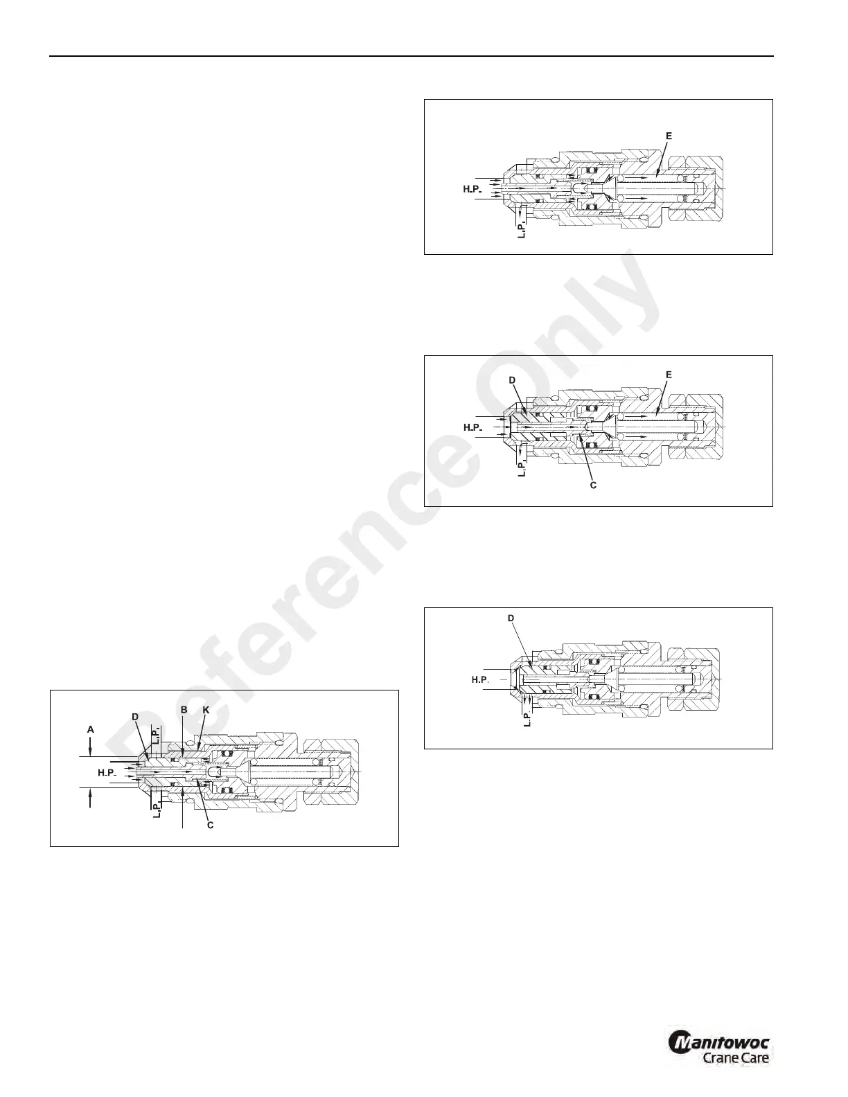
A relief valve is in communication between the high pressure
port “HP” Figure 4-10 and the low pressure area “LP”. Oil is
admitted through the hole in poppet “C” and because of a
differential area between diameters “A” and “B”, relief valve
poppet “D” and check valve poppet “K” are tightly sealed.
The oil pressure in the high pressure port “HP” Figure 4-11
has reached the setting of the pilot poppet spring force and
unseats pilot poppet “E” and oil flows around the poppet,
through the cross drilled holes and to the low pressure area
“LP”.
The loss of oil behind poppet “C” Figure 4-12 affected by the
opening of pilot poppet “E” causes poppet “C” to move back
and seat against pilot poppet “E”. This shuts off the oil flow to
the area behind relief valve poppet “D” and causes a low
pressure area internally.
The imbalance of pressure on the inside as compared to that
of the high pressure port “HP” forces the relief valve poppet
“D” Figure 4-13 to open and relieve the oil directly to the low
pressure chamber “LP” in the valve. Oil then flows back to
the hydraulic oil tank.
Main Relief Valve Pressure Test Procedure
NOTE: The hydraulic oil must be at operating temperature
(120° - 130° F (45° - 54° C).
Swing Circuit Main Relief Valve Setting Test
1. With the engine shut off and parking brake engaged,
install a 0 - 5000 psi (0 - 345 bar) pressure gauge to the
test connection on the pressure side of the swing section
of the hydraulic pump (Figure 4-14).
2. Disconnect both hoses at the swing motor. Plug the
hoses and cap the fittings on the motor.
3. Start the engine and accelerate it to full rpm.
Reference Only
 Loading...


