STRUCTURALS 5540F/YB5515 SERVICE MANUAL
11-30
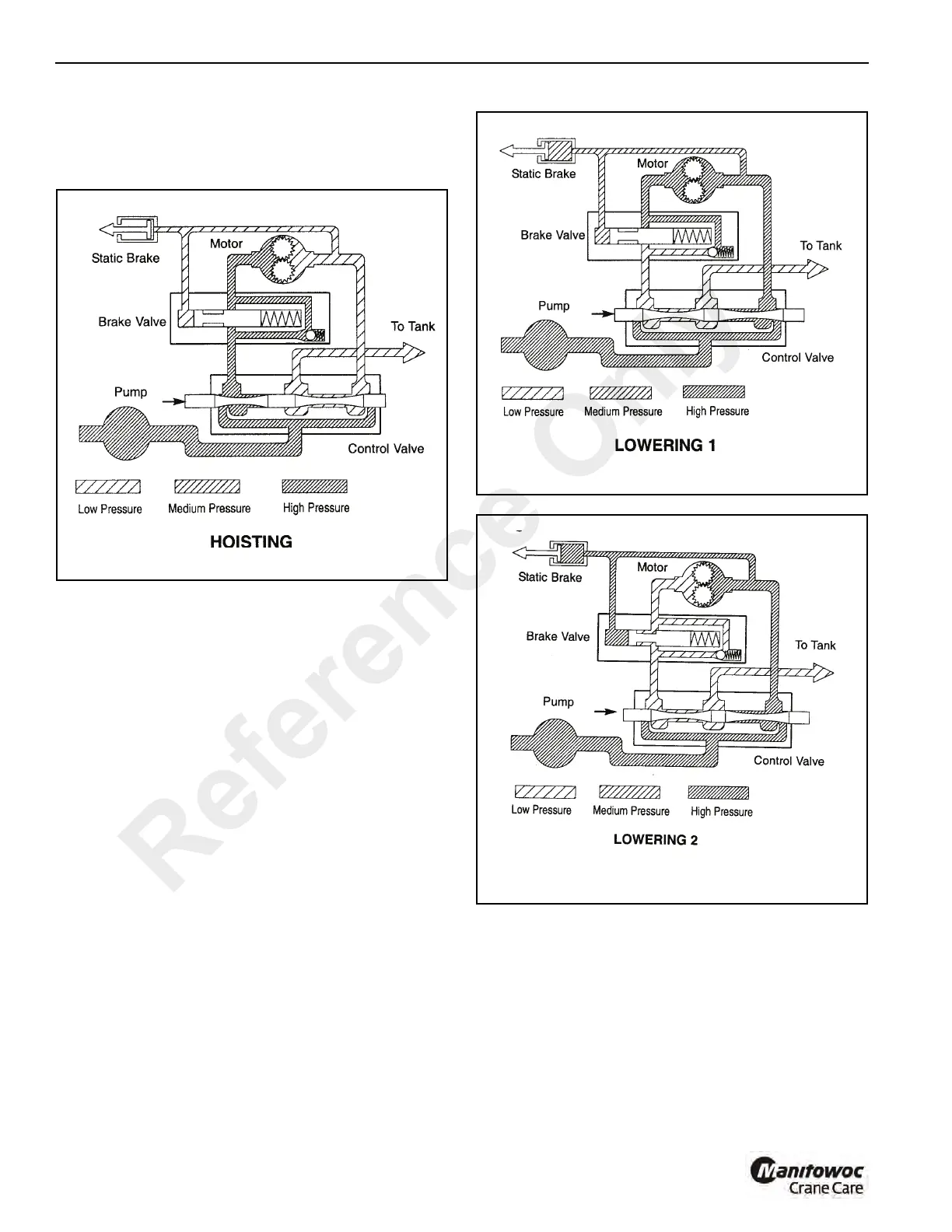
oil, under pressure, from the pump is sent through the main
control valve to the counterbalance valve; opening the check
valve. Oil flows through the check valve to the motor, rotating
in the hoisting direction. See Figure 11-55.
When the control valve is placed in the lowering position, the
spring loaded, pilot operated spool valve remains closed
(Figure 11-56) until sufficient pilot pressure is applied to the
end of the spool valve to shift it against spring pressure;
opening a flow passage (Figure 11-57). After the pilot
operated spool valve cracks open, the pilot pressure
becomes flow-dependent and modulates the spool opening
which controls the lowering speed.
The static brake system has thee operating components
(see Figure 11-54):
1. Spring applied, multiple friction disc static brake.
2. Brake clutch assembly.
3. Hydraulic piston and cylinder.
The static brake is released by the brake valve pilot pressure
at a pressure lower than that required to open the pilot
operated spool valve.This sequence assures that dynamic
Reference Only
 Loading...


