Home
Manitowoc
Construction Equipment
Grove YB5515
Manitowoc Grove YB5515 Service Manual
4
of 1
of 1 rating
412 pages
Give review
Manual
Specs
To Next Page
To Next Page
To Previous Page
To Previous Page
Loading...
HYDRAULIC SYSTEM
5540F/Y
B5515 SER
VICE
MANUAL
4-8
Published 10-21-2010, Control# 198-04
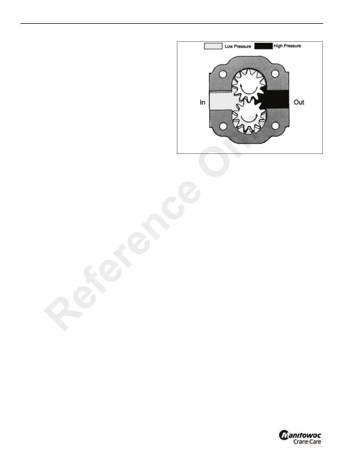
Lubrication of intern
al components is provided
through
passag
es in the hydraulic pump bod
y and grooves in the
pressure plates. A l
ip seal on the shaft
and o-rings between
the sections prevent external leakage in the pump.
FIGURE
4-
2
a0389
Reference
Only
71
73
Table of Contents
Table of Contents
3
Directional Reference
13
Identification Plates
13
Specifications
14
General Maintenance
17
Cleanliness
17
After Cleaning
17
Removal and Installation
17
Disassembly and Assembly
18
Pressing Parts
18
Locking Devices
18
Wires and Cables
18
Shims
18
Hoses and Tubes
18
Bearings
19
Gaskets
19
Batteries
20
Hydraulic Systems
20
Electrical System
21
Fatigue of Welded Structures
21
Loctite
22
Fasteners and Torque Values
22
Weld Studs (Table 1-10)
26
Hydraulic Fitting
26
Wire Rope
28
General
28
Environmental Conditions
28
Dynamic Shock Loads
28
Lubrication
28
Precautions and Recommendations During Inspection or Replacement
28
Wire Rope Inspection (Running Ropes and pendant Cables)
29
Keeping Records
29
Frequent Inspection
29
Wire Rope Inspection (Boom Extension and Retraction Cables)
30
Wire Rope Inspection/Replacement (All Wire Rope)
30
Seizing Wire Rope
31
Installing Flex-X 35 Wire Rope
32
Procedures for Cutting and Preparing Flex-X 35
32
Hydraulic Pressure Testing
33
O-Ring, Seal and Elastic Nut Replacement
33
Section 2 Safety Practices
35
Section 2
35
Introduction
37
Signal Words
37
Equipment Considerations
38
Personal Considerations
38
General Considerations
39
Operational Considerations
39
Final Word
40
Section 3 Electric System
41
Section 3
41
General
43
Comparing Electrical System to a Hydraulic System
43
Magnetism
43
Main Electrical System
43
Fuses
44
Wire Harnesses
44
Charging System
45
Alternator and Voltage Regulator
45
Batteries
45
Battery Maintenance and Charging
45
Pressure Switch
45
Special Precautions
45
Voltmeter
45
Starting Circuit
46
General Inspections
46
Starting Circuit Check
46
Instrument and Light Circuits
47
Gauges
47
General
47
Light Bulbs
47
Wire Harnesses
48
Engine Wire Harness
48
Instrument Panel Wire Harness
48
Accessory Circuits
53
Anti-Double Blocking System (Figure 3-6)
53
Load Moment Indicator (LMI) System (Figure 3-1)
55
Optional Engine Shutdown
57
Heater
58
Section 4 Hydraulic System
63
Section 4
63
Technical Data
65
General Description
65
General
65
Hydraulic System
65
Troubleshooting
66
Troubleshooting Aids
66
Troubleshooting Procedures
66
Troubleshooting Guides
67
Suction, Pressure and Return Circuits
71
General
71
Hydraulic Pump
71
Main Relief Valves
76
Main Control Valve
77
Adjusting Main Relief Valve Pressure Settings
80
Lift Circuit
82
General
82
Oil Flow
82
Holding Valve
83
Lift Cylinder Leakage Check
83
Hydraulic Swivel
86
Crowd Circuit
87
General
87
Holding Valve
87
Oil Flow
87
Crowd Cylinders Leakage Test
90
Hydraulic Swivel
90
Main Winch Circuit
90
General
90
Oil Flow
90
Brake Holding Valve
91
Hydraulic Swivel
91
Swing Circuit
94
General
94
Oil Flow
94
Anti-Double Blocking System
94
System Function
95
Outrigger Circuit
98
General
98
Oil Flow
98
Load Holding Valves
101
Outrigger Cylinder Leakage Check
101
Axle Lockout Circuit
101
General
101
Oil Flow
101
Component Repair
105
Hydraulic Pump Repair
105
Main Control Valves
108
Swing Motor
113
Hydraulic Swivel
119
Hydraulic Cylinders
122
Section 5 Preventative Maintenance
129
Introduction
131
Spark Arresting Mufflers
131
Safety List
131
Lubricants
131
Maintenance Records
131
Special Maintenance
131
Delivery Inspection
131
After First 50 Hours of Operation (New Cranes)
132
Cranes Not in Regular Use
132
Preventive Maintenance
132
Maintenance Schedule and Checklist
132
Lubrication Points
135
Scheduled Maintenance
139
Daily (Walk-Around) Inspection
139
Component/System Checks
139
Inspections
139
Hours of Operation (Weekly)
143
Clean the Air Cleaner Dust Cup
143
Wire Rope Inspection
143
Grease Fittings
144
Lubricate Parking Brake
144
Lubricate the Boom Slides
144
Hours of Operation (Two Weeks)
146
Check Wheel Nut Torque
146
Inspect the Fan Belts
146
Hours of Operation (Monthly)
147
Clean Battery and Cables
147
Inspect the Hydraulic Hoses
147
Clean the Radiator
148
Lubricate the Swing Gear and Pinion
148
Lubricate the Wire Rope
148
Replace the Crankcase Oil and Filter
149
Torque Critical Bolts
149
Hours of Operation (3 Months)
150
Inspect Parking Brake Pads
150
Inspect the Tires
150
Replace Air Cleaner Element
150
Replace Fuel Filter (Diesel Engine)
150
Add Grease to the Swing Gearbox
151
Add Rust Inhibitor to Engine Cooling System
151
Lubricate the Outrigger Slides
151
Spark Plug Gap (Gasoline Engine)
151
Check Axle Housing Lubricant Level
152
Check Wheel Hub Lubricant Level
152
1000 Hours of Operation (6 Months)
153
Check Winch Gearbox and Brake Lubricant Levels
153
Replace the Transmission Oil and Filter
153
Replace the Axle Housing Lubricant
154
Replace Axle Wheel Hub Lubricant
155
Replace the Hydraulic Oil
156
Replace the Winch Gearbox and Brake Lubricant
156
Replace the Hydraulic Oil Filter
157
Replace L.P.G. Inline Filter
157
2000 Hours of Operation (Yearly)
158
Check Swing Gear/Pinion Backlash
158
Replace the Spark Plugs (Gasoline Engine)
158
Replacing the In-Line Fuel Filter (Dual Fuel Engine)
158
Replacing the Engine Coolant
158
Miscellaneous Maintenance
159
Batteries/Charging System
159
Inspect the Crane Structure and Booms for Damage
159
Testing the Load Moment Indicator (Optional)
159
Checking the Charging System
159
Charging the Battery
159
Replacing the Battery
159
Fuel System
160
Fuse Replacement
160
Fuel Storage
160
Carwell® Rust Inhibitor
162
Protecting Cranes from Rusting
162
Cleaning Procedures
162
Inspection and Repair
163
Application
163
Areas of Application
163
Section 6 Engine and Engine Systems
167
Engine Crankcase System
169
Crankcase Oil Data
169
Engine Performance
169
Engine RPM
169
Engine Types
169
General
169
Governor
169
Engine Cooling System
170
Coolant Requirements
170
Radiator Cap and Overflow Bottle
171
Thermostat
171
Engine Electrical System
171
Engine Fuel System
171
Diesel Engine Fuel System Description
171
QSB Engine Electronic Controlled Fuel System Units
172
Types of Fuel to Use
172
Checks and Adjustments
173
Throttle Linkage Adjustment
173
Engine Air Intake System
173
Engine Exhaust System
173
Removal and Installation
175
Removal
175
Installation
176
Dual Fuel Engine and Engine Systems
176
General
176
Engine Types
176
Engine Performance
176
Engine RPM
177
Governor
177
Crankcase System
177
Crankcase Oil Data
177
Engine Cooling System
177
Coolant Requirements
177
Radiator Cap and Overflow Bottle
178
Thermostat
178
Engine Electrical System
178
Engine Fuel Systems
179
Fuel Injected Dual Fuel System
179
Fuel Tank
180
Fuel Level Sender and Gauge
180
Fuel Pump
180
Types of Fuel to Use
180
Engine Air Intake System
181
Engine Exhaust System
181
Electronic Fuel Injection System
181
Fuel Injection Components
183
Checks and Adjustments
193
Troubleshooting
194
Removal and Installation
195
Section 7 Transmission and Torque Converter
199
Technical Data
201
General Technical Data
201
Clutch Solenoid Technical Data
202
Description of Operation
203
General
203
Torque Converter
203
Transmission
203
Reverser Clutch
209
Hydraulic 2/4 Wheel Drive Unit - Spring On/Pressure off
210
Hydraulic 2/4 Wheel Drive Unit - Pressure On/Spring off
212
Hydraulic 2/4 Wheel Drive Unit - Pressure On/Spring off (Cont'D)
213
Troubleshooting
214
General Troubleshooting
214
Hydraulic 2/4 Wheel Drive Unit (Spring On/Pressure OFF)
218
Hydraulic 2/4 Wheel Drive Unit (Pressure On/Spring OFF)
219
Troubleshooting
220
Water Contamination
220
Cooler Test Procedure
221
Flushing Procedure
221
General Procedure
221
Inspection
221
Stalling the Torque Converter
221
Clutch Pressure (Forward Clutch Given in Example)
223
Mainline Pressure
223
Pressure and Flow Tests
223
Pump Flow
223
Converter in Pressure
224
Converter out Pressure/Oil Cooler Flow Rate
224
Lubrication Pressure
224
Transmission Repair
227
Removal
227
Servicing the Torque Converter
227
Installation
228
Removal
230
Servicing the Transmission
230
Transmission Gearbox Repair
230
Assembly
237
Assembly
248
Solenoid Valve Disassembly and Assembly
248
Assembly
250
Hydraulic 2/4 Wheel Drive Unit Disassembly and Assembly (Pressure On/Spring off Type)
253
Hydraulic 2/4 Wheel Drive Unit Disassembly and Assembly (Pressure On/Spring off Type)7-53
253
Hydraulic 2/4 Wheel Drive Unit Disassembly and Assembly (Spring On/Pressure off Type)
255
Hydraulic 2/4 Wheel Drive Unit Disassembly and Assembly (Spring On/Pressure off Type)7-55
255
Section 8 Axles/Drive Shafts/Wheels and Tires
259
Description
261
Front Axle
261
Rear Axle
261
Front Drive Axle
261
Technical Data
262
Rear Drive Axle
262
Rear Non-Drive Axle
263
Front Drive Axle Repair
264
Removal
264
Installation
264
Special Tools
264
Replacing the Pinion Oil Seal
266
Axle Hub Repair
267
Drive Head Repair
271
Rear Axles Repair
279
Removal
279
Installation
279
Service Tools
279
Replacing the Pinion Oil Seal
279
Axle Hub Repair
279
Drive Head Repair (Drive Axles Only)
284
Drive Shafts
286
Drive Shafts
287
Removal
287
Disassembly
287
Inspection
288
Assembly
288
Installation
289
Lubrication Procedure
290
Wheel & Tires
290
Tire Inflation
290
Wheel Stud Nuts
290
Grove
291
Technical Data
293
Front Axle Brakes
293
Rear Axle Brakes
293
Accumulator
293
Accumulator Charging Valve
293
Priority Flow Control Valve
293
Description
294
Service Brake System
294
Parking Brake System
297
Maintenance and Adjustments
297
Service Brake Bleeding
297
Parking Brake Bleeding
298
Parking Brake Adjustment
298
Accumulator Charging
299
Residual Brake System Pressure
299
Tests
299
Brake Piston Seal Leakage Test (Front Axle Only)
299
Service Brake Repair
301
Front Axle Brakes
301
Rear Axle Brakes
304
Parking Brake Repair
305
Lining Kit Replacement
305
Repair Kit Installation
307
Seal Kit Installation
308
Brake Modulating Valve Repair
310
Removal
310
Disassembly
310
Assembly
310
Installation
310
Troubleshooting
311
Service Brakes
311
Grove
313
Section 10
313
Units Without Return-To-Center Steering
315
Technical Data
315
Description
315
Crab Steering
315
Four-Wheel Steering
315
Two-Wheel Steering
315
Relief Valve Pressure Check and Adjustment
319
Pressure Adjustment
319
Pressure Check
319
Units with Return-To-Center Steering
320
Technical Data
320
Description
320
General
320
Steering Modes
320
Two-Wheel Steering
320
Crab Steering
323
Four-Wheel Steering
323
Relief Valve Pressure Check and Adjustment
326
Steering Proximity Switches
326
General
326
Principle of Operation
326
Sensor Operation and Spacing Checks
328
Steering Orbitrol
331
Description
331
Orbitrol Repair
331
Steering Cylinder
338
Cylinder Repair
338
Special Tools
338
Technical Data
338
Section 11 11
343
Booms
345
General
345
Extending the Fourth Boom Section
345
Retracting the Fourth Boom Section
347
Removal of Boom Assembly
348
Installation of the Boom Assembly
348
Disassembly
349
Assembly
355
Wire Rope, Sheaves and Hoist Blocks
356
Wire Rope Description
356
Wire Rope Safety
357
Inspecting Wire Rope
357
Inspection of Sheaves
357
Wire Rope Lubrication
358
Wire Rope Installation
358
Installation of Socket and Wedge
358
Installation of a New Wire Rope
359
Main Winch (Tulsa Model)
360
Theory of Operation
360
Repair
362
Removal
362
Winch Assembly
362
Motor Group
364
Brake Section
365
Troubleshooting
372
Main Winch (Braden Model)
373
Theory of Operation
373
Winch Operation
373
Description of Winch (Figure 11-54)
373
Repair
376
Removal
376
Winch Assembly
378
Planet Carrier Service
385
Motor Support-Brake Cylinder Service
386
Brake Clutch Service
390
Winch Tension Roller Subassembly Service
392
Troubleshooting
394
Bearing, Mast and Related Parts
395
General
395
Mast Bearing
396
Mast Bearing Bolts
397
Inspection for Bearing Wear
397
Replacing the Mast Bearing
397
Removal
397
Swing Gearbox and Pinion
398
Adjustment
398
Installation
398
Maintenance
398
Swing Gearbox Repair (Tulsa Gearbox)
400
Removal
400
Disassembly
400
Swing Gearbox Repair (Braden Gearbox)
403
Inspection
403
Installation
403
Removal
403
Disassembly
403
Assembly
403
Outriggers
405
Outrigger Monitoring System (OMS)(Optional-Standard in North America)
405
Installation
405
Removal
405
Cylinder Removal
406
Cylinder Installation
406
Other manuals for Manitowoc Grove YB5515
Operator's Manual
134 pages
4
Based on 1 rating
Ask a question
Give review
Questions and Answers:
Need help?
Do you have a question about the Manitowoc Grove YB5515 and is the answer not in the manual?
Ask a question
Manitowoc Grove YB5515 Specifications
General
Brand
Manitowoc
Model
Grove YB5515
Category
Construction Equipment
Language
English
Related product manuals
Manitowoc Grove YB5515-2
152 pages
Manitowoc Grove YB5520
144 pages
Manitowoc Grove 5540F
134 pages
Manitowoc Grove RT890E
24 pages
Manitowoc Grove RT540E
160 pages
Manitowoc GROVE GMK3060
906 pages
Manitowoc Grove GRT8100
216 pages
Manitowoc GROVE GMK6400
354 pages
Manitowoc Grove GRT8120
448 pages
Manitowoc Grove TMS700E
352 pages
Manitowoc Grove RT530E-2
168 pages
Manitowoc GROVE GMK5150L
1040 pages