14 Wizard user manual
Connecting the data link
1 Connect a data cable to the controller’s output. If controller has a 5-pin output, use
a 5-pin male to 3-pin female adaptor cable (P/N 11820005).
2 Lead the data cable from the controller to the first fixture. Plug the cable into the
fixture’s data input.
3 Connect the output of the fixture closest to the controller to the input of the next
fixture. If connecting two fixtures with opposing polarity on pins 2 and 3, insert a
phase-reversing cable between the two fixtures.
4 Continue connecting fixtures output to input. Up to 32 devices may be connected
on a serial link.
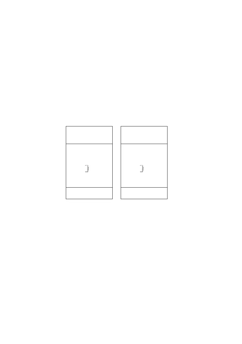
5 Terminate the link by inserting a male termination plug (P/N 91613017) into the data
output of the last fixture. A termination plug is simply an XLR connector with a 120
ohm, 0.25 W resistor soldered across pins 2 and 3.
Male XLR
1
2
3
Male
P/N 91613017
120
Female XLR
1
2
3
Female
120
Termination PlugTermination Plug
P/N 91613018