PREPARING THE TRACTOR
10
cod. G19503950
3
Preparing the tractor
CAUTION: Avoid injury. Proper ballastings is required for safe operation of your sickle bar mower
,03257$175HIHUWRWKHWUDFWRURSHUDWRUPDQXDOIRUSURSHUEDOODVWLQJLQIRUPDWLRQDQGWLUHLQÀDWLRQ
$USP372
5HIHUWRWKHWUDFWRURSHUDWRUPDQXDOIRUFRUUHFWEDOODVWLQJDQGWLUHSUHVVXUHGHSHQGLQJRQLQVWDOOHG
equipment.
Parking instruction
6WRSYHKLFOHRQDOHYHUVXUIDFHQRWRQDVORSH
'LVHQJDJH372
(QJDJHWKHSDUNEUDNH
6723WKHHQJLQH
5HPRYHWKHNH\
%HIRUH\RXOHDYHWKHRSHUDWRU¶VVHDWZDLWIRUHQJLQHDQGDOOPRYLQJSDUWVWR6723
Stay clear of rotating drivelines
Entanglement in rotating driveline can cause serious injury
or death:
:HDUFORVH¿WWLQJFORWKLQJ
6723WKHHQJLQHDQGEHVXUH372GULYHOLQHLVVWRSSHG
before getting near it.
Installing sickle bar on tactor
The sickle bar can be hitched to I, II or quick coupler cate-
gory tractor equipped with a universal three-point coupling.
DANGER
Application of any implement to a tractor is
a very dangerous operation and must only
be carried out with the utmost care in com-
pliance with the instructions.
The correct tractor/sickle bar position is established by
setting the implement at such a distance from the tractor
that the universal coupling remains 2-4 inches from its ma-
ximum closing position. Now proceed in the following way:
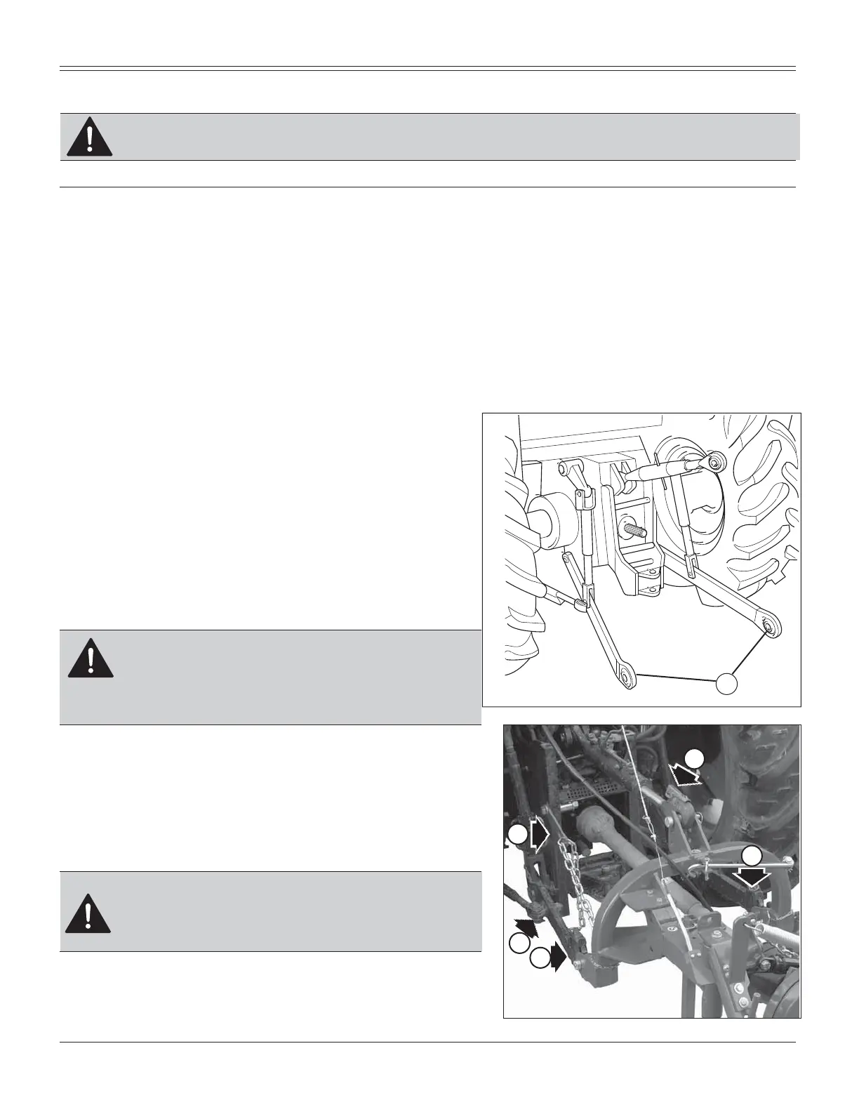
1. Back tractor into position and align draft links (A, Fig.
6) with draft link brackets on sickle bar.
CAUTION: Before you work around hitch:
6723HQJLQH
/2&.SDUNEUDNH
),50/<EORFNPRZHURQKRUL]RQWDOVXUIDFH
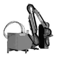
2. Connect the upper third-point and correctly regulate by
means of the adjuster (B, Fig. 7). Place plate (C, Fig. 7)
at the left side of the hicht integral with the same pin.
Lock in place with the snap-in split pins (D, Fig. 8).
E
F
C
B
Fig. 7
I
Fig. 6
A