OPERATING - MECHANICAL LIFTING SYSTEM
20
cod. G19503950
3
Mowing
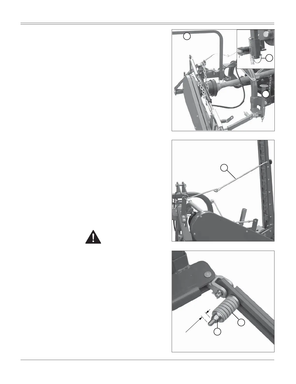
5HPRYHWKHVXSSRUWV3DQG4)LJDQGUHPRXQW
them, upside-down in their seat . Install spring locking
pin in order to secure parking stand (R).
T
U
5HPRYHWLHURG6)LJIURPWKHFXWWLQJDUP
5HPRYHVDIHW\KRRN')LJUHTXLUHGRQO\IRUWUDQ-
VSRUWDWLRQDQG¿WLWEDFNLQWKHVORWSRVLWLRQHGDERYHWKH
chassis.
7KHVLFNOHEDULV¿WWHGZLWKDVDIHW\GHYLFHIRUSURWHFWLRQ
against obstacles. If this device is tripped by impact with
an obstacle, stop the tractor without raising the cutting
arm. Check that the cardan shaft has not become se-
perated, if so, reassemble it. Position the safety tie
rod parallel to the ground, and reverse the tractor
until the safety tie rod hooks up again. If the tie rod
releases easly, adjust spring (T, Fig. 31) using nut (U,
Fig. 31) which should be tightened half turn at a time.
ATTENTION
A spring compression other than that indicated in Figure
31 (0.59 inches) can make the safety device ineffective.
For successful mowing and to avoid jamming, we advise
you to:
Set and maintain the power take-off at a constant
rate of 540 rpm to ensure correct blade frequency;
maintain an engine speed of 1800÷2000 rpm.
FRPSDWLEO\ZLWKWKHVRLOFRQGLWLRQVDQGWKHW\SHRIJUDVV
maintain a steady work speed: no slower than 5 mph to
favor the discharging of the mown grass and no faster
than 6.2 mph to avoid breaking or damaging the machi-
ne’s structure.
LIWKHJUDVVLVWDQJOHGRUÀDWWHQHGNHHSWKHFXWWLQJEDU
grazing the ground.
Fig. 31
Fig. 30
Q
P
R
Fig. 29
S
0.59 inches
(15 mm)