OPERATING - MECHANICAL LIFTING SYSTEM
19
cod. G19503950
3
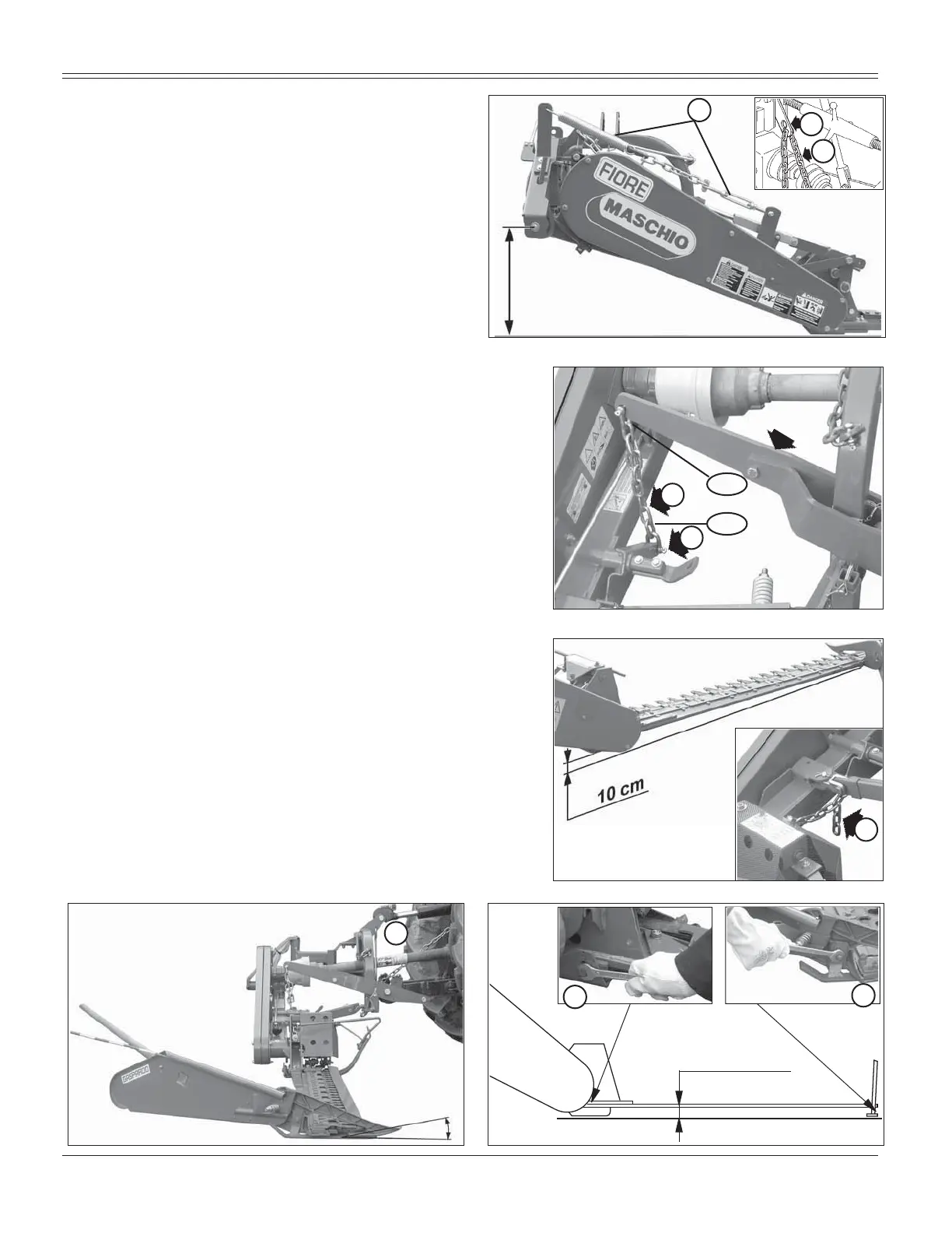
&RQQHFWRQHHQGRIWKHFKDLQ))LJWRWKH
mower using the supplied pin and the other end
to a stationary point on the tractor. Adjust the
height of the mower to the ground (19.6 to 21.7
inches, Fig. 24) by moving the rings of the chain
(F, Fig. 24) in the hole on the plate (G, Fig. 24).
When the lifter is lowered, this precaution will
constantly hold the mower at the same height
from ground level.
$FWRQWKHWLHURGVSULQJ.)LJWREULQJWKH
internal skid close to the ground (without dischar-
ging the weight on the ground), lightening the
load of the machine on the cutter bar.
$GMXVWLQJ WKH KRLVWLQJ FKDLQ + )LJ VR WKDW GXULQJ
mowing the hoisting arm (I, Fig. 25) is free to move up and
down; in this way, the cutting arm can follow any unevenness
of the ground.
So that the mower will work well, we advise you to
¿[WKHFKDLQ+)LJWRWKHOLIWLQJDUP,)LJ
DWWKHOHYHORIWKHWKRUWKOLQNRIWKHFKDLQ
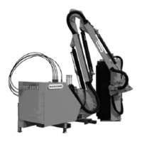
$GMXVWWKHKHLJWRIWKHFXWWLQJDUPIURPWKHJURXQGZLWK
chain (J, Fig. 26). Lower the mower; when the external
tip of the arm touches the ground, the inner shoe must
remain approximately 10 cm. above ground level (Fig.
26). Adjust by moving the chain links.
6RWKDWWKHPRZHUZLOOZRUNZHOOZHDGYLVH\RXWR¿[
the chain (J, Fig. 25-26) to the equalizer (L, Fig. 25-26),
leaving the last links of the chain free.
$GMXVWLQFOLQDWLRQRIWKHFXWWLQJDUPWHHWKXVLQJWLHURG
(M, Fig. 27).
For low, moist and thick fodder, tilt the teeth downwards
by shortening the tie rod (M, Fig. 27).
For ground with rocks and stones tilt the teeth upwards
by lengthening the tie rod (M, Fig. 27).
$GMXVWWKHFXWWLQJKHLJKW)LJE\PRYLQJWKHPRZLQJ
bar on the holes of the inner mowing bar support (N),
and, turning the nut of the outer mowing bar support (M),
bring it level with the ground.
Min. 1,2 inches
0D[LQFKHV
O
Fig. 28
Fig. 26
Fig. 25
I
1°
7°/8°
M
Fig. 27
19.6 ÷ 21.7
inches
F
Fig. 24
G
K
J
N
L
H