SERVICE
36
cod. G19503950
3
Checking the clearance tolerance
Fig. 63
Fig. 64
302 mm
30 mm
1 mm
1.18 inches
11.9 inches
thicknes
~0.04 inches
Fig. 65
Fig. 66
Z2
Z1
ATTENTION
It is absolutely essential to disengage the trac-
tor pto, lower the mowing machine, switch off
the tractor, ensure that this is at a complete
standstill and remove the key before servicing,
adjusting the implement for work. All assembly
operations must be carried out on a work bench.
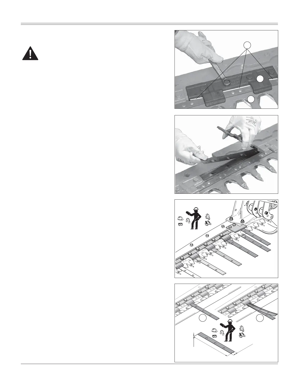
Before activating the mower, one must periodically check
that the blade holder rod (M, Fig. 63) and the upper blade
guides (N) are coupled properly.
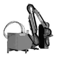
After many hours of work, wear of the blade guide material
may be seen, and this will cause an increase in the coupling
tolerance with the tooth blade.
An excessive coupling tolerance between the parts results
in material entering between the same, causing likely
breakage of the cutting blades or parts of them, also com-
promising the quality of the cut.
In contrast, a reduced coupling tolerance generates a
strong sliding friction of the blade with consequent bre-
akage of the blade holder rod, the blade head or other
elements of the hinge (connecting-rod assembly).
It is therefore advisable to restore the correct tole-
rance!
The check must be carried out on all blade guides (Fig. 65)
using a ~0.04 inches (1 mm) thick shim plate, supplied.
$OZD\VXVHSHUVRQDOSURWHFWLYHHTXLSPHQW
The tolerance allowed for optimal coupling is deter-
mined by the insertion of a single plate (Z1, Fig. 66).
,IDSODWHGRHVQRW¿WEHWZHHQWKHWHHWKEODGHDQGWKHEODGH
guide one must add a shim (Fig. 63-64);
If instead two coupled plates can be inserted (Z2, Fig. 66)
one must remove a shim to restore the optimal coupling
tolerance conditions.
CAUTION
:KHQ¿WWLQJWKHEODGHJXLGHLWLVLPSRUWDQWWROHDYHD
coupling tolerance of about ~0.04 inches (1 mm) with
the sections holder rod (L, Fig. 63).
L
M
N