SERVICE
40
cod. G19503950
3
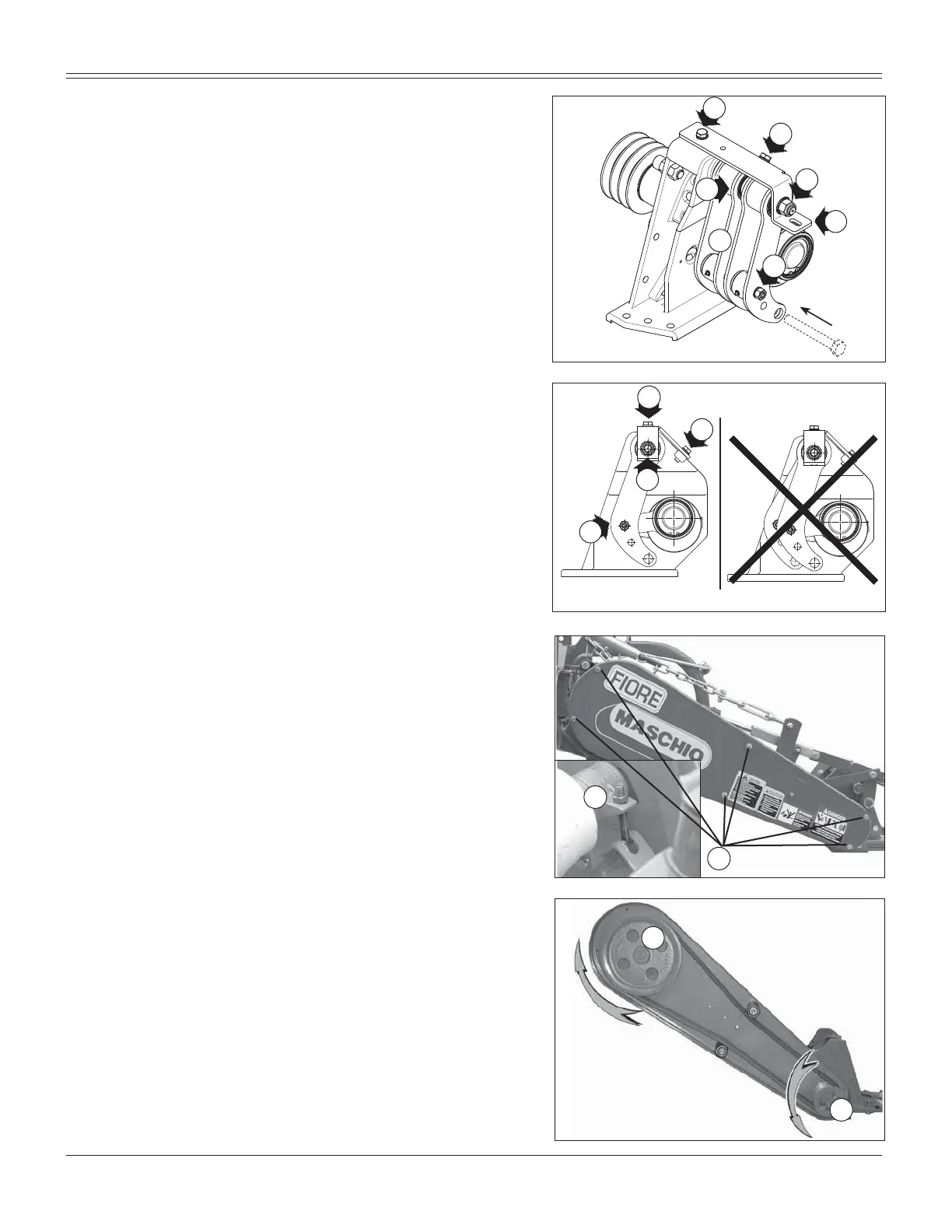
Replacing the anti-vibration yokes
Dismantling
Remove the protection.
Remove the expansion pins (M, Fig. 74).
Loosen and remove screws L, H, I (Fig. 74).
Remove the support (N, Fig. 74).
Remove the yokes (P, Fig. 74).
Assembly
1) Insert the new yokes with the intermediate spacer (O,
Fig. 74).
5H¿WWKHVXSSRUWDQGVFUHZV/+,ZLWKRXWWLJKWHQLQJ
them.
3) Couple the yokes to the connecting rods and fasten
them with the expansion pins.
4) Align the yokes properly using a pin or screw (M20)
(Fig. 74).
5) Tighten screws H and I.
6) Tighten screw L securely.
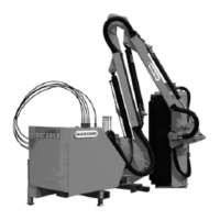
CAUTION: do not tighten the screws without having alig-
ned the yokes correctly (P, Fig. 75).
5H¿WWKHSURWHFWLRQ
Verifying the assembly
The bolt must be removed manually with no force; if ne-
cessary, repeat the tightening steps of screws “H”, “I” and
then “L”.
Replacement of belts
8QVFUHZWKHVFUHZV4)LJDQGUHPRYHWKHSUR-
tective casing.
/RRVHQWKHEHOWWHQVLRQHUFRPSOHWHO\5)LJ
5HSODFHWKHZRUQEHOWVZLWKQHZRQHV
3XWWKHVHDWWKHRSWLPXPWHQVLRQXVLQJWKHEHOWWHQVLRQHU
Belt play should not exceed 1 inch.
3XWWKHSURWHFWLYHFDVLQJEDFN LQSRVLWLRQDQG¿[ LWLQ
place with the screws (Q, Fig. 76).
Replacement of pulleys
Notes for replacement of pulleys, if necessary.
8QVFUHZWKHVFUHZV4)LJDQGUHPRYHWKHSUR-
tective casing.
/RRVHQWKHEHOWWHQVLRQHUFRPSOHWHO\5)LJ
5HPRYHWKHEHOWV
To replace the driving pulley (S, Fig. 77), turn it clockwise; vi-
ceversa, turn the driven pulley (T, Fig. 77) counterclockwise.
Fig. 77
Fig. 76
H
I
L
N
M
O
P
H
I
L
P
Q
R
S
T
Fig. 74
Fig. 75