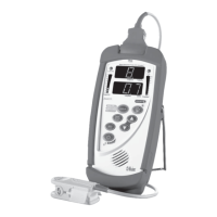
Rad-57 Signal Extraction Pulse CO-Oximeter Operator’s Manual 4-1
4
operation
Introduction
To operate the Rad-57 Pulse CO-Oximeter effectively, the operator must:
■ Know how the oximeter derives its readings (see Section 1, Pulse CO-Oximetry)
■ Be familiar with its controls and operation.
■ Understand its status and alarm messages (see Section 5, Alarm Identification,
System Messages and Section 6, Troubleshooting).
Basic Operation
GENERAL SETUP AND USE
1. Inspect the oximeter case for damage.
2. Ensure that the batteries are correctly installed.
3. Connect a Rainbow Sensor or a Red Patient Cable with an LNOP, LNOPv or LNCS
sensor
to the Patient Cable connector of the oximeter. Make sure it is a secure
connection and the cable is not twisted, sliced or frayed. See Section 5, Messages,
to view messages that may be displayed pertaining to sensors and cables.
4. Select a sensor that is compatible with the oximeter before connecting it to the
patient cable. See Section 8, Sensors and Patient Cables. If using a single patient
adhesive or disposable sensor, check that the emitter (red light) and the detector are
properly aligned. If using a reusable sensor, make sure it opens and closes smoothly.
Remove any substances that may interfere with the transmission of light between the
sensor’s light source and detector.
5. Attach the sensor to the patient. Refer to the Directions for Use of the sensor.
6. Properly align and insert the male-connector end of the sensor into the female-
connector end of device (or patient cable). Make sure it is a secure connection.
7. Press the Power button to turn the oximeter on.
8. Verify all front-panel indicators momentarily illuminate and an audible tone is heard.
9. Verify the front panel display is free of alarm and system failure messages (see
Section 5, Alarms and Messages) and the battery indicator shows sufficient charge
(see Section 4, Battery Level Indicator).
10. Verify that the display shows the current device settings in the following order:
■ SpO
2
Low Alarm Limit
■ SpO
2
High Alarm Limit
■ Pulse Rate
Low Alarm Limit
■ Pulse Rate
High Alarm Limit
■ SpCO
Low Alarm Limit*
■ SpCO
High Alarm Limit*
■ SpMet
Low Alarm Limit*
■ SpMet
High Alarm Limit*
■ Sensitivity
■ Averaging Time
■ FastSat: On or Off
*See Model Summary for applicable device.