HOW IT WORKS
10 May 2010 / Mass Combi 12/2500-100; 24/2500-60; 48/2500-35; 48/5000-70 / EN
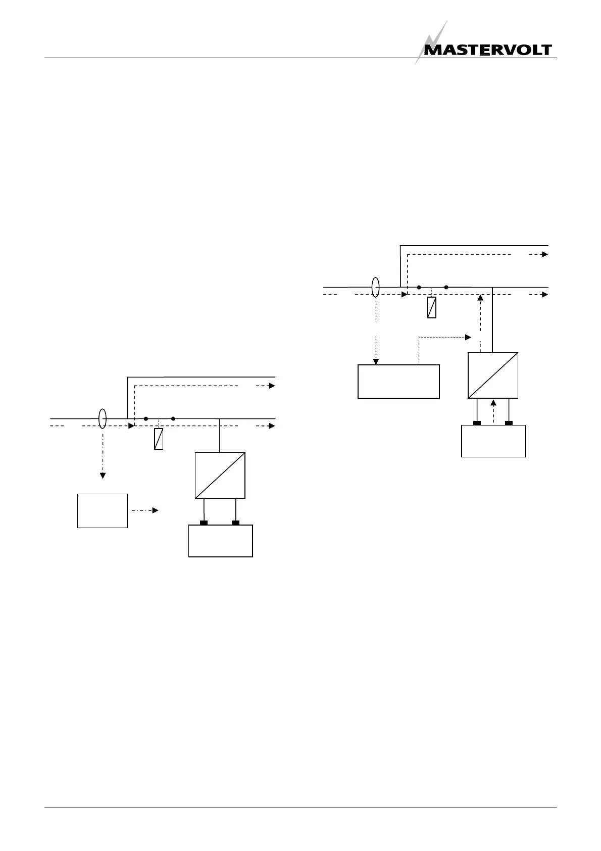
See figure 6.
Here the Power Sharing level is set to a 6 Amps while the
AC outputs consume a total of 1 + 3 = 4 Amps. This
means that only 6 – 4 = 2 Amps is left over for charging.
With 12V batteries this will result in a maximum charge
current of approx. 30A DC
Although the Power Sharing level can be set by means of
the DIP-switches locally on the Mass Combi (see section
6.2.1), we recommend the use of an optional remote
control panel, like the Remote APC or Masterlink MICC.
With this remote panel you can select the available shore
current (fuse) of each marina or camping site in a very
easy way.
When the total connected AC load reaches the level of the
Power Sharing setting (6A), there will be no power left
over to charge the battery. This means that the charge
current of the Mass Combi will be reduced to 0A. See
figure 7.
3.3.4 Generator / mains support function
(selectable)
If the demand for AC power still increases, the external AC
circuit breaker may still trip if nothing is done. This problem
can be solved by the Generator / mains support function. If
the total demand for energy exceeds the maximum
external power supply, energy can be added to the AC
outputs “POWER” and “SHORT BREAK” by means of the
inverter. This appliance can be automatically connected in
parallel with the external power supply.
See figure 8
Here the AC-input is still limited to 6 Amps. This is not
enough to supply the total load (4 + 9A = 13A) connected
to the AC outputs.
When the Generator / mains support function is enabled,
the inverter will supply the remaining 13 – 6 = 7A. This
means that the restricted amount of external AC power will
be compensated by energy which is stored in the
batteries.
Later, when the AC load has dropped below the setting of
the Power sharing function again, the battery charger of
the Mass Combi will commence to recharge the batteries.
For safety reasons the transfer relay is immediately
switched off when incoming AC power fails in operation so
that there will never be a high voltage on the shore cable
inlet when it is not connected.
AC INPUT
AC OUTPUT
“POWER”
AC OUTPUT
“SHORT BREAK”
AC
DC
BATTERIES
GENERATOR /
MAINS SUPPORT
FUNCTION
6A
4A
9A
Max. 6A-AC
7A
Figure 8: Generator / mains
support function
Approx.
130A-DC
@12V
AC INPUT
AC OUTPUT
“POWER”
AC OUTPUT
“SHORT BREAK”
AC
DC
BATTERIES
6A
4A
2A
Max. 6A-AC
0A
Approx.
0A-DC
@12V
Figure 7:
Power sharing
POWER
SHARING
FUNCTION

 Loading...


