INSTALLATION
20 May 2010 / Mass Combi 12/2500-100; 24/2500-60; 48/2500-35; 48/5000-70 / EN
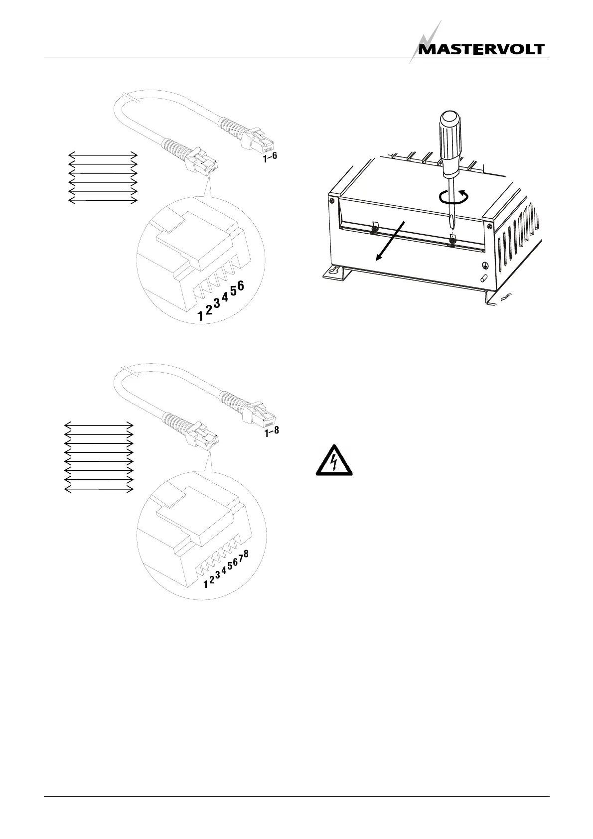
Figure 19: Modular communication cable, 6 pole, cross
wired. For connection of remote control panels
Figure 20: Modular communication cable, 8 pole, cross
wired. For communication between two Mass Combi’s
(parallel operation)
5.5 REMOVAL OF THE FRONT PANEL
Figure 21
See figure 21. Steps:
1 Loosen the two Phillips screws that secure the front
cover plate for two turns.
2 Slide the front cover plate from the cabinet
(downwards).
The connectors for the battery, the AC and the remote
panel are now visible. See figures 22 and 23
WARNING
The front panel may never be removed while
the Mass Combi is still connected to a power
source!
1
2
3
4
5
6
6
5
4
3
2
1
1
2
3
4
5
6
7
8
8
7
6
5
4
3
2
1
Step 1
2x
Step 2
 Loading...


