OPERATION
14 May 2010 / Mass Combi 12/2500-100; 24/2500-60; 48/2500-35; 48/5000-70 / EN
4 OPERATION
The Mass Combi is a fully automatic inverter / charger
system. Under normal circumstances there is no need for
adjustment or operation besides switching on and off.
WARNING
Never disconnect any of the wiring during
operation of the Mass Combi
4.1 INDICATORS
See figure 15. The operation of the Mass Combi is
displayed by means of LED indicators at the front side of
the housing. If the Mass Combi is activated and as long as
none of the red indicators are illuminated, no failure is
detected and the unit is operating normally.
4.2 SWITCHING ON AND OFF
The only control on the Mass Combi itself is the main
switch (see figure 15) on the front of the unit. This switch
controls On, Off and Ch. (Charger only)
4.2.1 Switching on
The Mass Combi can be activated by switching the main
switch to the “ON” position.
If two Mass Combis are installed in parallel,
the slave unit will only operate properly after
the master unit was switched on first.
If you use a remote control panel, press the on/off button
on the remote control panel.
After switching on expect a three till five second delay
before the unit is activated. The LED-indicators will blink
several times, indicating the installed software version
(see section 9.2 for explanation).
If AC power is available on the AC input and within the
specified limits, the Mass Combi will switch to Charger
Mode and will commence to charge the batteries. At the
same time the internal transfer relay will pass the AC
power to the AC output “SHORT BREAK”.
If the AC power from the external AC-source is unavailable
or outside the specified limits, the unit will come on as an
inverter. Inverter overload protection, built-in idle mode
circuitry, transfer switching, power sharing and battery
charger regulation will all function automatically.
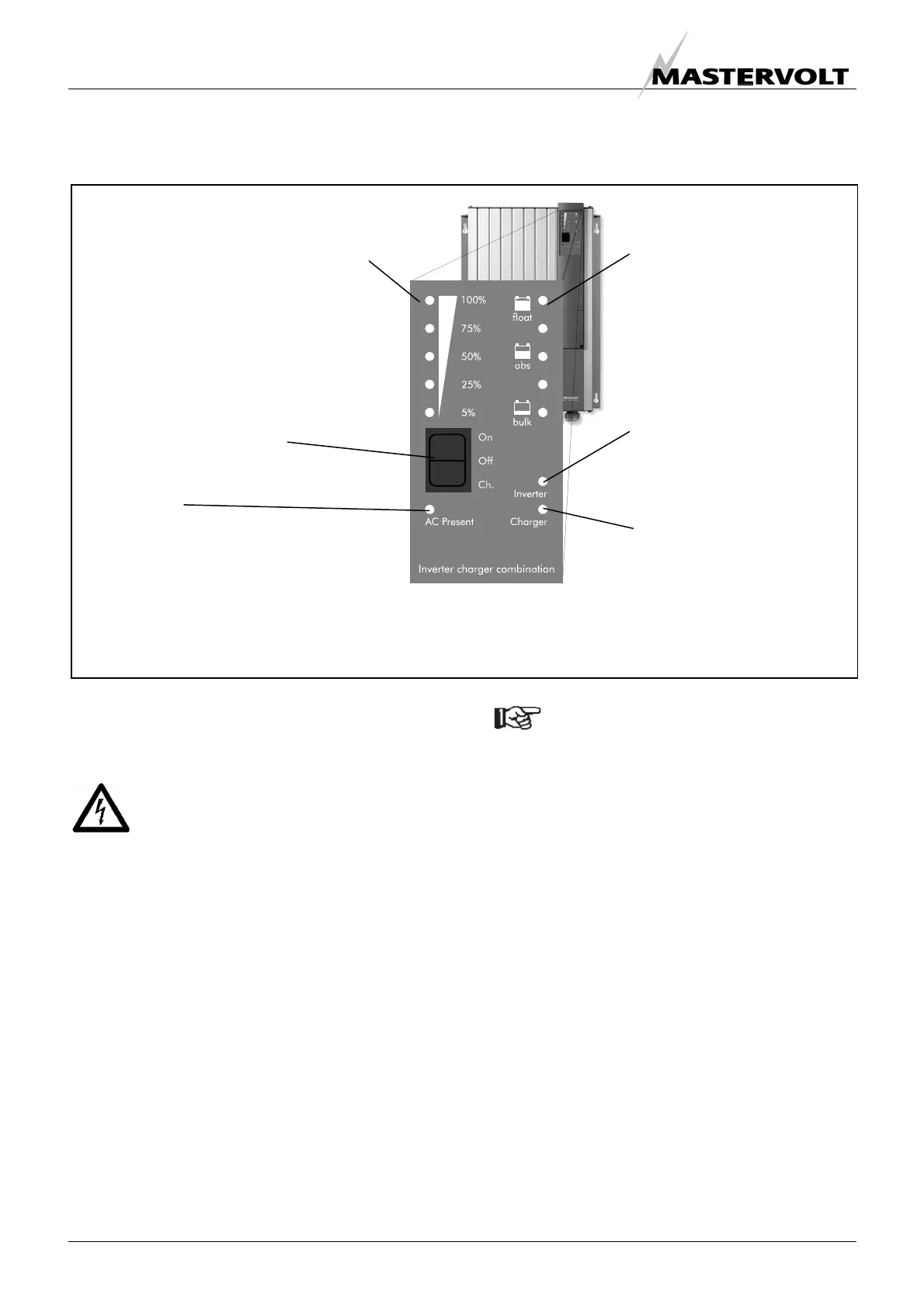
Figure. 15: LED indicators
Power ba
Charger mode: Displays the actual DC
charge current as a percentage of the
maximum charge current
Inverter mode: Displays the actual AC
output power as a percentage of the
maximum output power
Charge cycle
Charger mode: Displays
the status of the charge
cycle: bulk, absorption or
float (see section 3.1.1).
Inverter mode: Displays
the approximate battery
voltage
Inverter LED
When illuminated green, the
Mass Combi is operating in
inverter mode
Charger LED
When illuminated green, the
Mass Combi is operating in
charger mode
AC Present
Illuminates when the incoming AC power (grid or
generator voltage) is available and according to
specifications.
When flashing fast, the incoming AC is outside
specifications.
When one of the indicators flashes or illuminates red, a failure is detected. The cause of
failure is explained in section 9.1
Main switch

 Loading...


