INSTALLATION
28 May 2010 / Mass Combi 12/2500-100; 24/2500-60; 48/2500-35; 48/5000-70 / EN
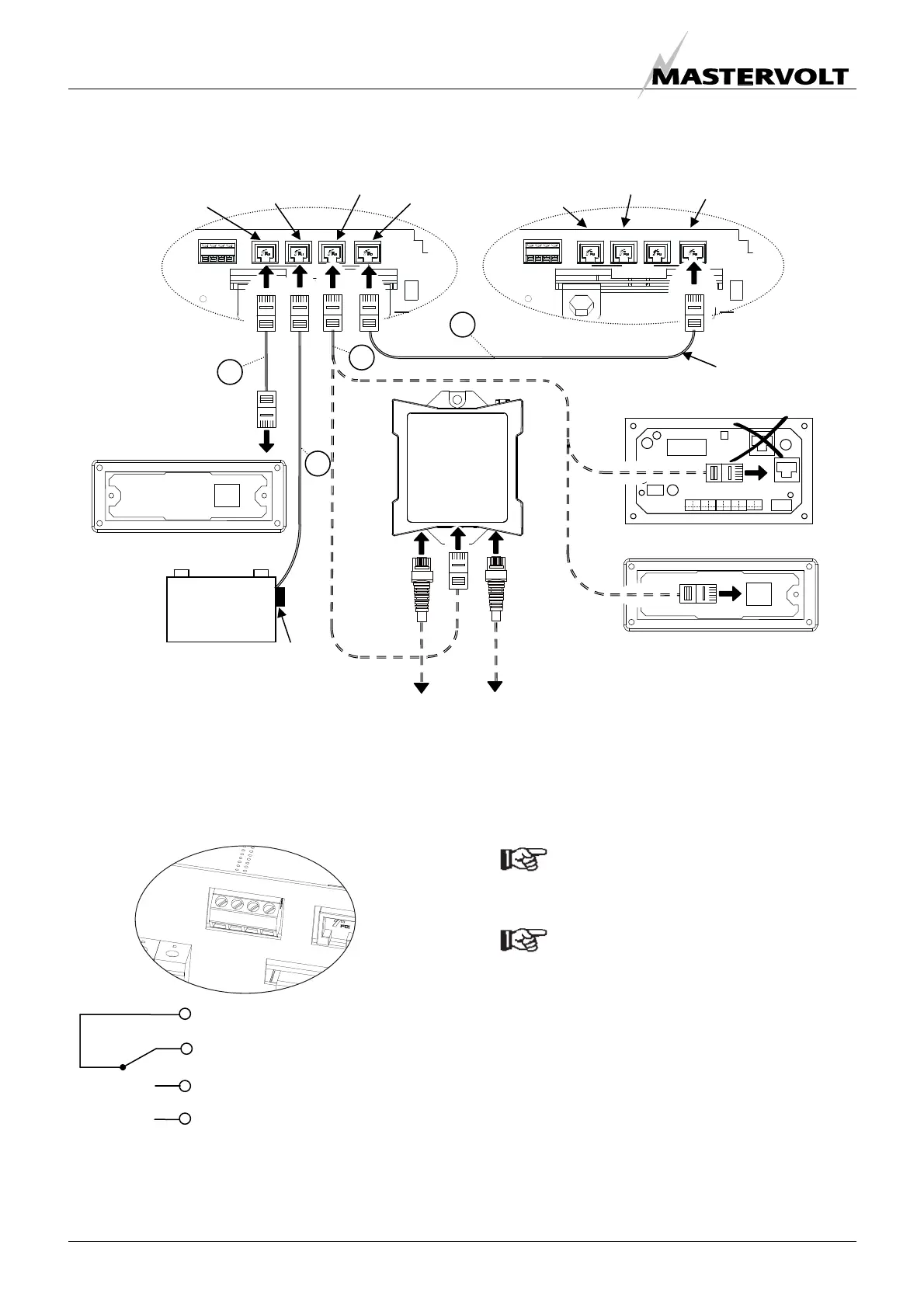
Figure 29:
Connection of remote control panels, battery temperature sensors and communication cable for parallel operation
5.8.3 Alarm contacts
Connectors 1 to 4 are internally linked as follows:
The alarm contact is switched to “Normally Open” in case
of an alarm situation, see section 3.6. Maximum switching
current: 1 Amp.
5.9 SETTINGS
See chapter 6 for DIP-switch settings.
NOTE:
Adjust the DIP-switches prior to
commissioning!
NOTE
When using a Masterlink MICC remote panel:
• See section 6.2.5 for DIP-switch setting at the
Mass Combi;
• See section 4.4 of the user’s manual of the
Masterlink MICC to enable the Mass Combi
setting.
1
-
2
-
3
-
4
1 (C) Common
2 (NC) Normally Closed
3 (NO) Normally Open
4 Not used
Figure 30: alarm contacts
APC panel (optional)
Masterlink MICC (optional)
MasterBus –
Serial interface
MASTERBUSREMOTE QRS232
+5A
NEG
TEMP. SENS
BATTERY
1 - 2 - 3 - 4
POS
MASTERBUSREMOTE QRS232
+5A
NEG
TEMP. SENS
BATTERY
1 - 2 - 3 - 4
POS
ICC panel (optional)
+ –
Service
Batteries
Temperature sensor
Communication
cable for parallel
operation
5
8
9
6
Mass Combi “A” (Master) Mass Combi “B” (Slave)
Remote
connection
(ICC panel)
Connector for
temperature
senso
QRS232
aansluiting
PARALLEL
connection
Remote
connection
(ICC panel)
PARALLEL
connection
Connector for
temperature
senso
MasterBus
network

 Loading...


