HOW IT WORKS
EN / Mass Combi 12/2500-100; 24/2500-60; 48/2500-35; 48/5000-70 / May 2010 13
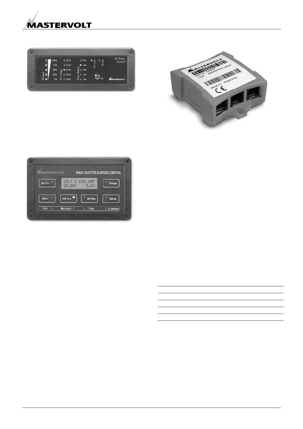
3.5.2 Remote panel APC
Figure 12: Remote panel APC
The APC panel has extended functions such as setting
remotely the Power sharing value and monitoring your
“AC-load”. This APC remote panel is optional (see chapter
11 for ordering information).
3.5.3 Masterlink MICC panel
Figure 13: Masterlink MICC panel
The Masterlink MICC panel (art. no 70403105) is a digital
remote panel that has additional features compared to the
ICC and APC panel. This sophisticated panel is not only a
remote control panel to switch on and off your Mass
Combi but also a battery consumption meter for read-out
of the exact state-of-charge of your battery by means of a
shunt. (included with the delivery of the Masterlink MICC)
When the battery is reaching a low voltage set point or a
low state-of-charge an alarm can be raised. This can be
used to start up the generator.
The information provided includes reading voltage,
current, consumed Ah, time remaining and remaining
capacity as a percentage of the maximum available
battery capacity. A well-lit LCD screen also displays direct
online data or historical information. A protective back box,
easy to install, is included as standard for protecting the
electronic components. This panel is suitable for
MasterVision, Mastervolt’s modular switchboard system.
3.5.4
MasterBus-serial interface
Figure 14: MasterBus-serial interface
The MasterBus – serial interface is standard included with
the delivery of the Mass Combi 12/2500-100, 24/2500-60,
48/2500-35 and 48/5000-70. With this interface you can
connect your Mass Combi to the MasterBus network: a
fully decentralized data network for communication
between the different Mastervolt system devices such as
the inverter, battery charger, generator, batteries and
many more. This enables monitoring and configuration
with a MasterView display or the MasterAdjust software.
See chapter 8 for details.
3.6 ALARM CONTACTS
The Mass Combi is equipped with an integrated alarm
function. External equipment can be controlled by the
potential free contacts of this alarm (see 5.8.3). The
maximum switch current of the relay is 1A. By default the
relay will be activated when the DC-voltage is out of range,
after a delay of 30 seconds. See table below. Other
functions can be programmed by means of MasterAdjust
software via the MasterBus – serial interface
Nominal voltage: 12V 24V 48V
Under voltage ON: 10.0V 20.0V 40.0V
Under voltage OFF: 11.0V 22.0V 44.0V
Over voltage ON: 16.0V 32.0V 63.0V
Over voltage OFF: 15.5V 31.0V 62.0V
Table 3

 Loading...


