INSTALLATION
EN / Mass Combi 12/2500-100; 24/2500-60; 48/2500-35; 48/5000-70 / May 2010 19
5.4 THINGS YOU NEED
Make sure you have all the parts you need to install the Mass Combi:
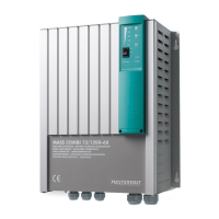
Mass Combi (included) 1 2
MasterBus – Serial interface + connection cable 60 cm (included) 1 1
Battery temperature sensor with cable and plug (included). 1 2
DC-cable to connect the positive DC connection (+) of the Mass Combi to the plus pole of the DC-distribution; for
specifications see section 10.1, maximum recommended length: 2m / 6ft, colour: preferably red or at least a
different colour to make a clear distinction between the positive and negative wire from the battery
1 2
DC-cable to connect the negative DC connection (–) of the Mass Combi to the negative pole of the DC-distribution;
for specifications see section 10.1, maximum recommended length: 2m / 6ft, colour: preferably black or at least a
different colour to make a clear distinction between the positive and negative wire from the battery.
1 2
DC-fuse holder with a DC-fuse, to be integrated in the positive DC-cable. For specifications see section 5.3.2. 1 2
Screws / bolts (Ø 6mm) (with plugs) to mount the cabinet to a surface. Use mounting materials which are suitable to
carry the weight of the Mass Combi
4 8
AC cable* to connect the AC input of Combi A to an external power source (e.g. a shore connection or a generator
set);
1 1
AC cable* to connect the external load to the AC “Power” output of Combi A. 1 1
AC cable* to connect the external load to the AC “SHORT BREAK” output of Combi A. 1 1
AC cable* to connect the AC “SHORT BREAK” outputs of both Combi A and B to each other. Maximum length: 15m – 1
Batteries. Refer to section 10.1 for specifications. X X
Appropriate and reliable cable terminals, cable lugs, battery terminals and cord end terminals X X
Modular communication cable 8 pole (maximum length 15m) for communication between the two Mass Combi’s.
See figure 20.
– 1
* Double insulated three wire cable with wire colours according to the locally applicable regulations. The applicable length and
wire diameter depend on the electrical installation (see section 5.3.1).
We recommend as a minimum tool kit:
• Socket wrench 13mm to fix the DC-input (battery) cables
• Flat blade screw driver 1.0 x 4.0 mm to fix the screw terminals
• Tools to fix the screws / bolts (Ø 6mm) with plugs to mount the cabinets to a surface
• Philips screw driver to open the connection area of the Mass Combi
Quantity needed for stand alone operation of one Mass Combi:
Quantity needed for parallel operation of two Mass Combi’s
 Loading...
