HOW IT WORKS
12 May 2010 / Mass Combi 12/2500-100; 24/2500-60; 48/2500-35; 48/5000-70 / EN
3.4 PARALLEL OPERATION
If 2500W of inverter power is not sufficient, yet another
identical Mass Combi can be connected in parallel to
double both the inverter power and the charge power. With
two units in parallel the total inverter power conversion will
be equally divided between the two units. To achieve this,
one of the units must be configured by means of a DIP-
switch setting as ‘master’ and the other as ‘slave’. See
figure 10. Once the configuration is established the master
tells the slave apparatus what to do. This communication
is done by the use of a modular communication cable
between the two units.
NOTE! : Only two units of the Mass Combi
12/2500-100, Mass Combi 24/2500-60 or the
Mass Combi 48/2500-35 can be connected in
parallel. Parallel operation of two units of the
Mass Combi 48/5000-70 is not possible.
See section 5.8.2 for connection and settings.
3.5 REMOTE MONITORING
Mastervolt offers several possibilities for remote
monitoring and control of the Mass Combi.
There are three remote panels available for the Mass
Combi. The Inverter Charger Control (ICC) panel and the
AC Power Control (APC) panel are specially designed for
the Mass Combi. The Mass Inverter Charger Control
(MICC) is a universal panel.
The remote panels are connected to the Mass Combi via a
modular communication cable with two RJ 12 connectors.
The maximum length of communication cable should not
exceed 15m/49ft. See chapter 11 for ordering information.
The Mass Combi can also be connected to the MasterBus
network. Therefore a MasterBus serial interface is
included with the delivery.
Note that it is not possible to connect all panels and the
serial interface at the same time. You should choose one
of the following options:
• No remote monitoring at all
• Remote panel ICC only
• Remote panels APC and ICC
• Masterlink MICC panel only
• MasterBus serial interface only
• MasterBus serial interface and Remote panel ICC
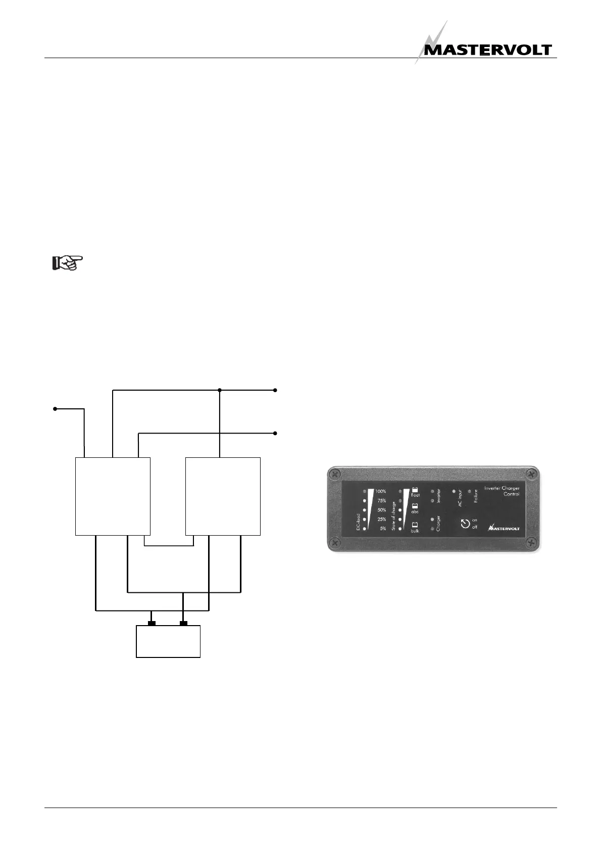
3.5.1 Remote panel ICC
Figure 11: Remote panel ICC
The ICC panel provides the same functions as the user
panel on the Mass Combi. However, with this remote
panel you have the convenience to operate the Mass
Combi remotely. See chapter 11 for ordering information)
AC OUTPUT
“SHORT BREAK”
BATTERIES
INPUT
OUTPUT
SHORT BREAK
OUTPUT
POWER
INPUT
OUTPUT
SHORT BREAK
OUTPUT
POWER
AC OUTPUT
“POWER”
AC INPUT
“master” “slave”
Modular
communication
cable
Figure 10:
Parallel operation

 Loading...


