INSTALLATION
24 May 2010 / Mass Combi 12/2500-100; 24/2500-60; 48/2500-35; 48/5000-70 / EN
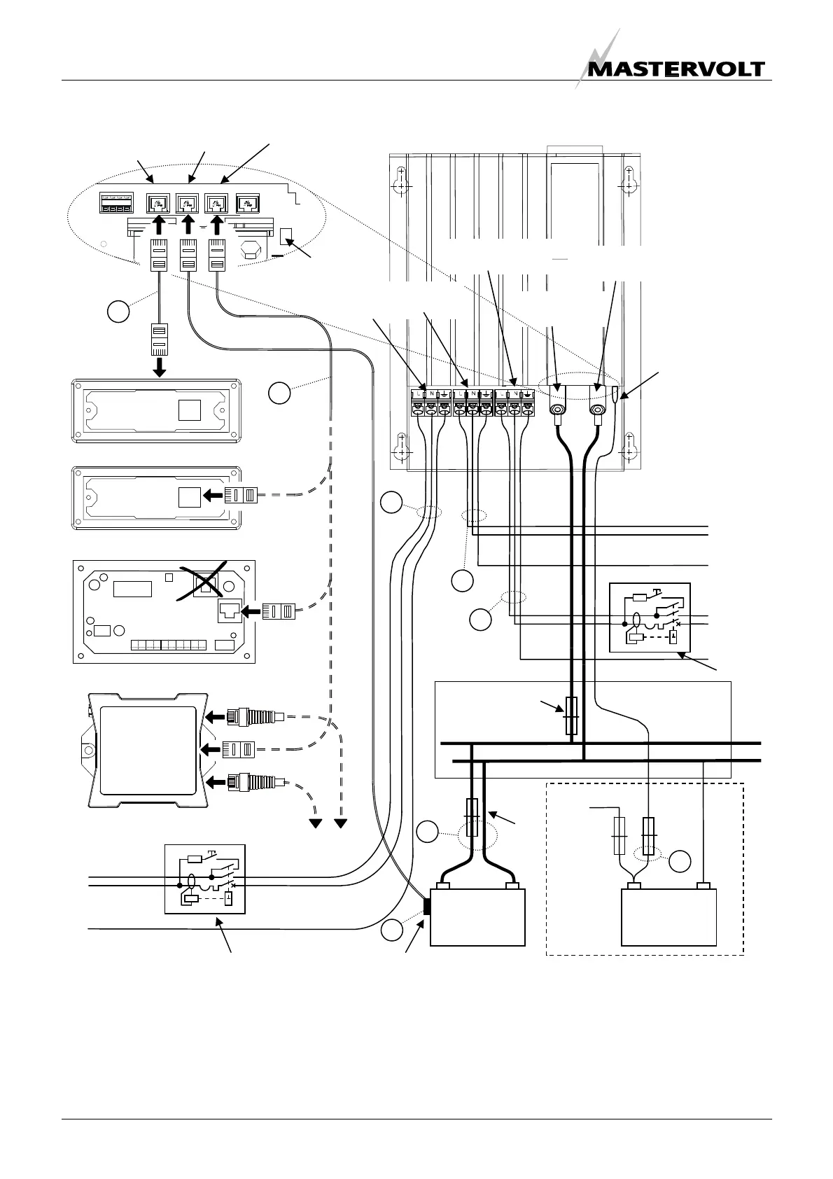
This schematic is to illustrate the general placement of the Mass Combi in a circuit. It is not meant to provide detailed wiring
instructions for any particular electrical installation.
Figure 27: installation drawing for one Mass Combi (stand-alone operation)
+ –
+ –
Starter battery
(optional)
Fuse
25A-T
Battery fuse
Combi fuse
Positive battery
terminal
Negative battery
terminal
Second 5A
charger output
L
N
PE
L
N
PE
L
N
PE
+
–
POWER
DC distribution
AC INPUT
To alternator
MASTERBUSREMOTE QRS232
+5A
NEG
TEMP. SENS
BATTERY
1 - 2 - 3 - 4
POS
AC output
SHORT BREAK
AC output
POWER
+ –
Service
Batteries
Remote
connection
(ICC panel)
Connector for
temperature
sensor
QRS232
connection
Second 5A
charger output
Temperature
sensor
AC input
ICC panel (optional)
APC panel (optional)
Circuit breaker / RCD
Max. 50Amps / 30mA
SHORT
BREAK
RCD
Incoming AC source
To AC-loads
OPTIONAL
Masterlink MICC (optional)
MasterBus – Serial interface
8
7
1
2
3
4
5
6
MasterBus
network

 Loading...


