INSTALLATION
26 May 2010 / Mass Combi 12/2500-100; 24/2500-60; 48/2500-35; 48/5000-70 / EN
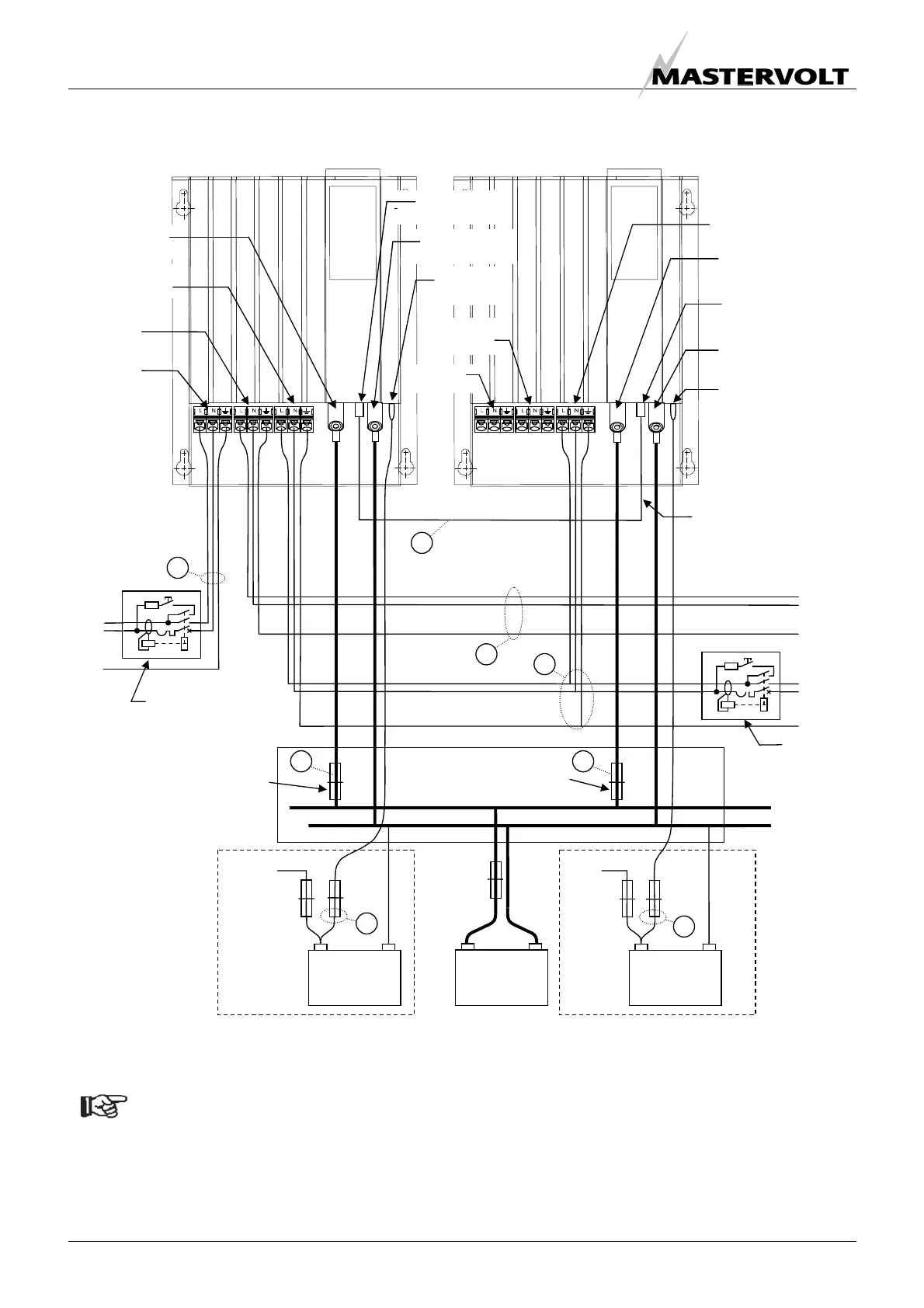
This schematic is to illustrate the general placement of the Mass Combi in a circuit. It is not meant to provide detailed wiring
instructions for any particular electrical installation.
NOTE: See also section 6.1.1 for DIP-switch settings
Figure 28: installation drawing for two Mass Combi’s (parallel operation). See also figure 29
+
Mass Combi “A”
(Master)
Mass Combi “B”
(Slave)
AC input
AC output
POWER
AC output
SHORT BREAK
+ –
Service
Batteries
+ –
Starter battery
A (optional)
+ –
Starter battery
B (optional)
Fuse
25A-T
Fuse
25A-T
Battery fuse
Combi fuse
Combi fuse
Positive battery
terminal
Negative battery
terminal
Second 5A
charger output
AC input
AC output
POWER
AC output
SHORT BREAK
Positive battery
terminal
Negative battery
terminal
Second 5A
charger output
L
N
PE
L
N
PE
+
–
SHORT
BREAK
DC distribution
AC INPUT
To alternator
To alternator
RCD
Circuit breaker
Max. 50Amps
RCD 30mA
L
N
PE
POWER
To AC loads
OPTIONAL OPTIONAL
+
PARALLEL
connecto
PARALLEL
connecto
Communication cable for
parallel operation
1
5
2
3
4 4
7
7

 Loading...


