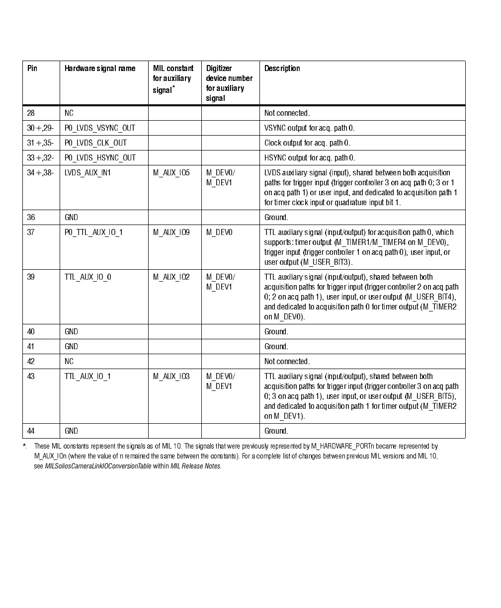
106 Appendix B: Technical information
The pinout for internal 10-pin auxiliary I/O connector is as follows. Refer to the
description of external auxiliary I/O connector 1 to establish if an auxiliary signal
is specific to an independent acquisition path and the type of signals that can be
routed onto it.
28 NC Not connected.
30+,29- P0_LVDS_VSYNC_OUT VSYNC output for acq. path 0.
31+,35- P0_LVDS_CLK_OUT Clock output for acq. path 0.
33+,32- P0_LVDS_HSYNC_OUT HSYNC output for acq. path 0.
34+,38- LVDS_AUX_IN1 M_AUX_IO5 M_DEV0/
M_DEV1
LVDS auxiliary signal (input), shared between both acquisition
paths for trigger input (trigger controller 3 on acq path 0; 3 or 1
on acq path 1) or user inpu t, and dedicated to acqu isition path 1
for timer clock input or quadrature input bit 1.
36 GND Ground.
37 P0_TTL_AUX_IO_1 M_AUX_IO9 M_DEV0 TTL auxiliary signal (input/output) for acquisition path 0, which
supports: timer output (M_TIMER1/M_TIMER4 on M_DEV0),
trigger input (trigger controller 1 on acq path 0), user input, or
user output (M_U SER_BIT3 ).
39 TTL_AUX_IO_0 M_AUX_IO2 M_DEV0/
M_DEV1
TT L auxiliary signal (input/output), shared between both
acquisition paths for trigg er in put (tri gger controlle r 2 on acq path
0; 2 on acq path 1), user input, or user output (M_USER_BIT4 ),
and dedicated to acquisition path 0 for timer output (M_TIMER2
on M_DEV0).
40 GND Ground.
41 GND Ground.
42 NC Not connected.
43 TTL_AUX_IO_1 M_AUX_IO3 M_DEV0/
M_DEV1
TT L auxiliary signal (input/output), shared between both
acquisition paths for trigg er in put (tri gger controlle r 3 on acq path
0; 3 on acq path 1), user input, or user output (M_USER_BIT5 ),
and dedicated to acquisition path 1 for timer output (M_TIMER2
on M_DEV1).
44 GND Ground.
*. These MIL constants represent the signals as of MIL 10. The signals that wer e previously represented by M_HARDWARE_PORTn became represent ed by
M_AUX_IOn (where the value of n remained the same between the constants). For a complete list of changes betw een previous MIL versions and MIL 10,
see
MILSoliosCameraLinkIOConversionTable
within
MIL Release Notes
.
Pin Hardware signal name MIL constant
for auxiliary
signal
*
Digitizer
device number
for auxiliary
signal
Description