FIFE-500 MAX Narrow Web Guide
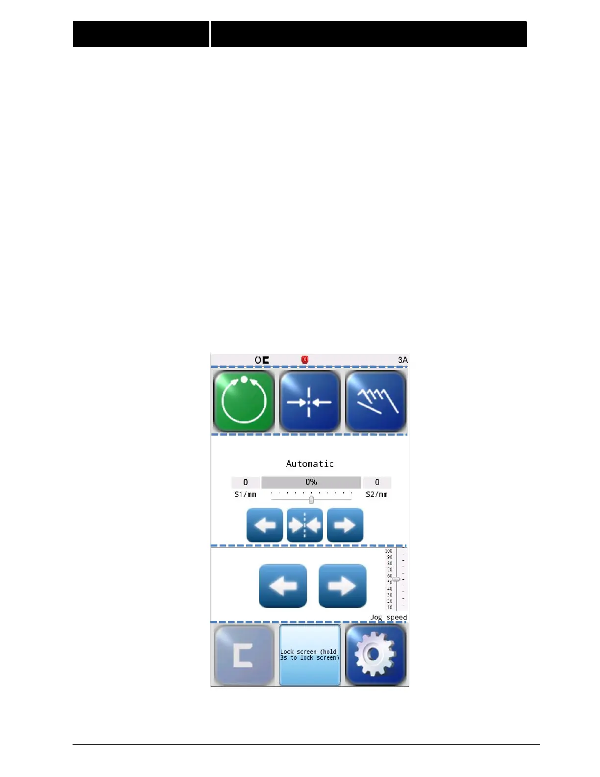
The Control Panel can also be configured in a vertical orientation. For the vertical orientation,
the following display descriptions apply. Refer to Figure 2 for the button locations.
The horizontal section (Section 1) along the top, above the line, contains the status bar
which always contains the menu number. It may also indicate statuses, errors, and
digital I/O.
The horizontal section near the top (Section 2), just below the line, contains the
Operation Mode selection buttons (Automatic, Servo Center, and Manual) and indicates
the current Operation Mode selection by displaying that button in a green color.
The section (Section 3) just below the Operation Mode buttons, indicates the current
Operation Mode, the selected sensor signal level in a bar graph, and the position of the
system guide point. S1/mm and S2/mm indicate the web position information acquired
by the sensor(Unit:mm).This section also contains the Guidepoint Shift buttons and the
Guidepoint Reset button.
The section (Section 4) below that, just above the Sensor Select and Setup buttons,
contains the Left and Right Jog buttons,Jog speed button.
The horizontal section along the bottom (Section 5) contains the Sensor Selection and
Setup buttons and indicates the current Sensor Mode selection by displaying the proper
sensor symbol in the Sensor Select button. This section also contains Lock screen button
that can lock or unlock the the screen.
Figure 2.
FIFE-500 MAX CONTROL PANEL
(90° AND 270° ROTATION)