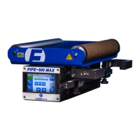
FIFE-500 MAX Narrow Web Guide
5. System Notes
1. Disconnect power from the FIFE-500 MAX before connecting or disconnecting any
cables.
2. All cable connectors must be tightened sufficiently to provide the required connection
for the cable shielding.
3. Sensor selection changes are allowed in Manual and Servo-Center modes, only..
4. In Automatic and Manual modes, the bar graph in the Control Panel indicates the signal
level of the selected sensor(s).
5. In Servo-Center mode, the bar graph in the Control Panel indicates the signal level of
the Servo-Center sensor.
6. When any command is detected on the Digital Port, a down arrow icon is displayed at
the top of the display.
7. The External Lock command is used to temporarily disable all motor commands. If
External Lock is commanded while in Automatic mode, when the External Lock
command is removed, the system reverts back to normal guiding operation. The
External Lock command is not to be used as an E-Stop.