FIFE-500 MAX Narrow Web Guide
3. Display Definitions
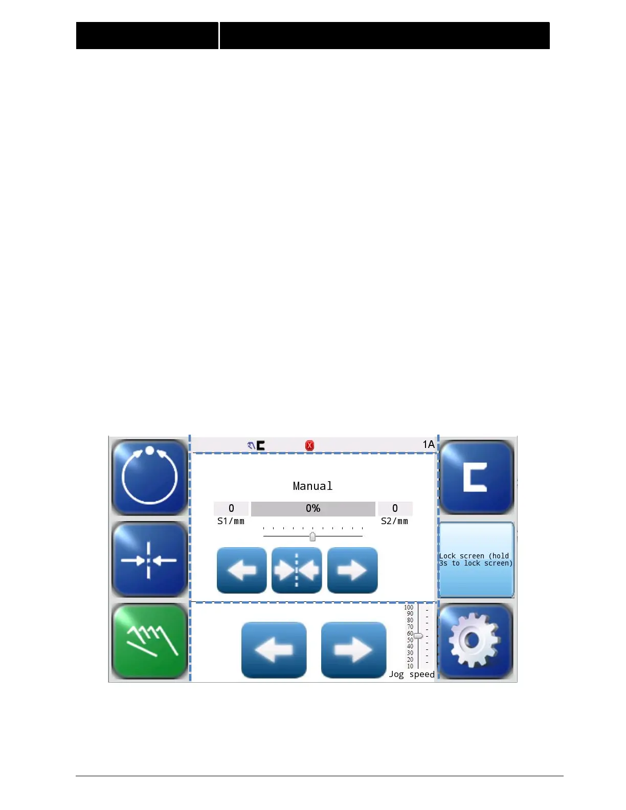
The FIFE-500 MAX uses a 5 inch Touchscreen for Operator command inputs and status
displays. This Control Panel is divided into 5 sections of information for which brief
descriptions follow. Refer to Figure 1 for the button locations in the standard, horizontal
Control Panel.
The vertical section on the left side (Section 1) contains the Operation Mode selection
buttons(Automatic, Servo Center, and Manual) and indicates the current Operation Mode
selection by displaying the corresponding button in a green color. (Other buttons are
blue)
The horizontal section (Section 2) at the top, above the line, contains the status bar
which always contains the screen number. It may also indicate statuses, errors, and
digital I/O.
The text in the middle section (Section 3) shows the current "operating mode", bar graph
showing web position information in this active sensor mode, and the slider below it
indicates the position of the system guide point. S1/mm and S2/mm indicate the web
position information acquired by the sensor(Unit:mm).This section also contains buttons
for Guidepoint Shift and Guidepoint Reset.
The lower middle section (Section 4) contains the Left and Right Jog buttons and Jog
speed button.
The vertical section(Section 5) on the right side contains the Sensor Selection and Setup
buttons and indicates the current Sensor Mode selection by displaying the proper sensor
symbol in the Sensor Select button.This section also contains Lock screen button that
can lock or unlock the the screen.
Figure 1.
FIFE-500 MAX CONTROL PANEL
(0° AND 180° ROTATION)