11921 Slauson Ave. Santa Fe Springs, CA. 90670 (800) 227-4116 FAX (888) 771-7713
11
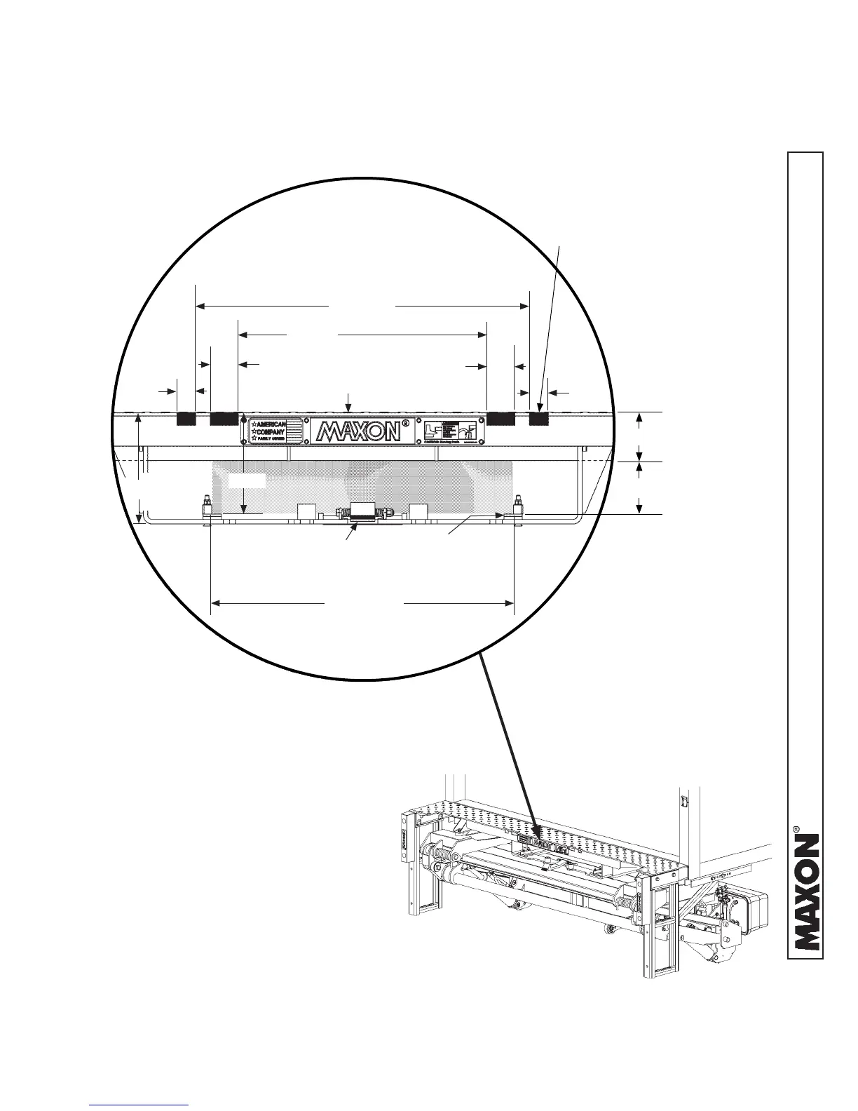
WALK RAMP BOX
CLEARANCE DIMENSIONS
(FOR REFERENCE ONLY)
FIG. 11-1B
2. Check for correct clearances between walk ramp, walk ramp box, and the extension
plate (FIGS. 11-1A and 11-1B) to prevent interference.
VEHICLE REQUIREMENTS - Continued
GPTWR LIFTGATE WITH WALK RAMP BOX
FIG. 11-1A
1-1/2”
WALK RAMP PAD
(2 PLACES)
WALK RAMP
LATCH
NOTCH
(4 PLACES)
2-1/4”
25” MIN.
32-1/2” MAX.
(RAMP WIDTH)
27-1/2”
20-1/2”
2-1/4”
1-1/2”
9-3/16”
8-3/8”
EXTENSION PLATE
H
SILL
H
RAMP
H
RAMP
= 8-3/8” - H
SILL
- 1/8” clearance
H
SILL
is the height of the vehicle body sill.
H
RAMP
is the height of the ramp (max).
 Loading...