11921 Slauson Ave. Santa Fe Springs, CA. 90670 (800) 227-4116 FAX (888) 771-7713
12
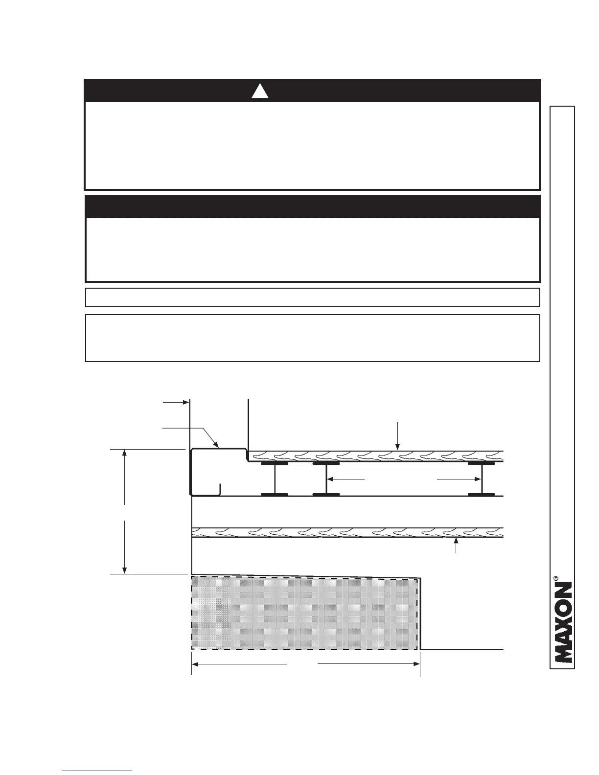
VEHICLE FRAME CUTOUT FOR GPTWR PLATFORM CLEARANCE
(TRUCK FRAME IS SHOWN)
FIG. 12-1
22”
10”
WOODEN SPACER
BODY FLOOR
BODY CROSS-
MEMBERS
LONG SILL
TRUCK BODY
TRUCK
FRAME
3. Fit the Liftgate to vehicle body by cutting vehicle frame as shown in FIG. 12-1.
REAR SILL
PLATFORM CLEARANCE CUTOUT AREA
(WITHIN DASHED LINES)
VEHICLE REQUIREMENTS - Continued
NOTE: The platform cutout area for truck frame, shown below, is required to prevent
frame interference when platform is being stowed and unstowed. For trailers,
refer to instructions supplied with trailer mounting kit for Liftgate.
To prevent aluminum platform from being damaged, make sure vehicle frame
is cut correctly and rear sills are modifi ed if over 4-1/8” in height. If the cutouts
are incorrect, platform may hit vehicle frame or underbody when stowing Lift-
gate. If rear sill is over 4-1/8” in height, bottom of the platform may hit the sill.
CAUTION
NOTE: Dimensions, shown in illustration below, are maximums except as indicated.
Incorrect modifi cation of vehicle frame and/or body could contribute to serious
mechanical failure of the vehicle. Serious injury to operator, motorists, and
bystanders could result. Installer is responsible for ensuring vehicle body and
frame modifi cation do not adversely affect the integrity of the body and frame.
If unsure about modifying vehicle, installer should consult truck/trailer body
manufacturer.
WARNING
!
 Loading...