11921 Slauson Ave. Santa Fe Springs, CA. 90670 (800) 227-4116 FAX (888) 771-7713
23
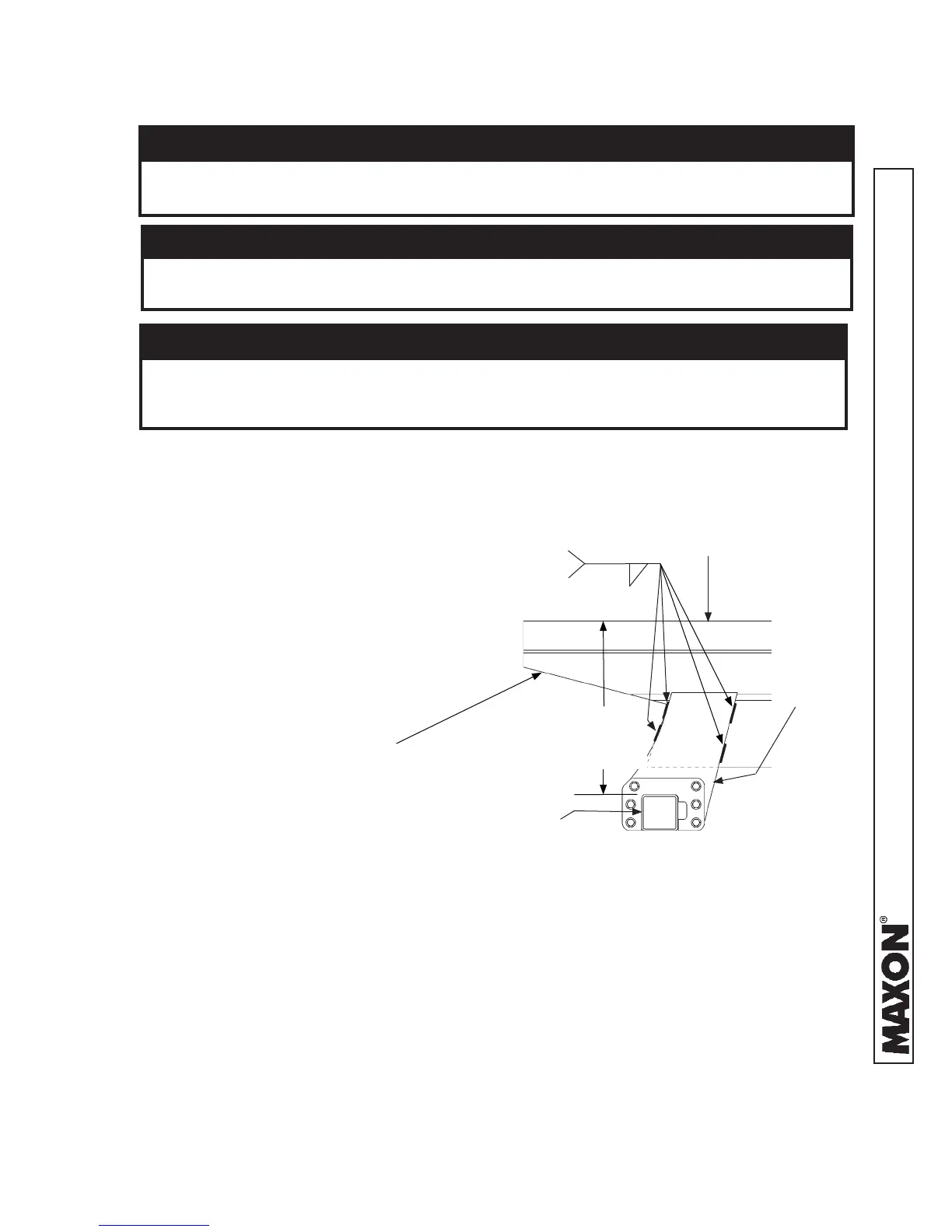
STEP 2 - WELD LIFTGATE TO VEHICLE - Continued
6. Weld the mounting plates to
vehicle frame as shown in
FIG. 23-1. Remove clamps.
5. Clamp both mounting plates
to vehicle frame. Check
the distance between bed
level and top of main frame.
Maintain the distance shown
in FIG. 23-1.
Prevent damage to hydraulic hoses. If welding next to hydraulic hoses, use a
protective cover such as a welding blanket to cover the hoses.
CAUTION
To protect the original paint system if equipped, a 3” wide area of paint must
be removed from all sides of the weld area before welding.
CAUTION
CAUTION
When using an electric welder, connect the welder ground to one of the parts
being welded, as close to the weld as possible. Failure to comply could result
in damage to cylinders and electrical parts.
VEHICLE FRAME CUTOUT
(TYPICAL TRUCK
FRAME SHOWN)
MOUNTING
PLATE
BED LEVEL
WELD TO VEHICLE FRAME AND MAIN FRAME
(RH SIDE SHOWN)
FIG. 23-1
2” LG. 4 PLACES
(TYPICAL - RH & LH
MOUNTING PLATES)
5/16”
* TOLERANCE IS +/- 1/4”
* 23-7/8” (GPTWR-25/-3)
* 22-3/8” (GPTWR-4/-5)
MAIN
FRAME
 Loading...