11921 Slauson Ave. Santa Fe Springs, CA. 90670 (800) 227-4116 FAX (888) 771-7713
26
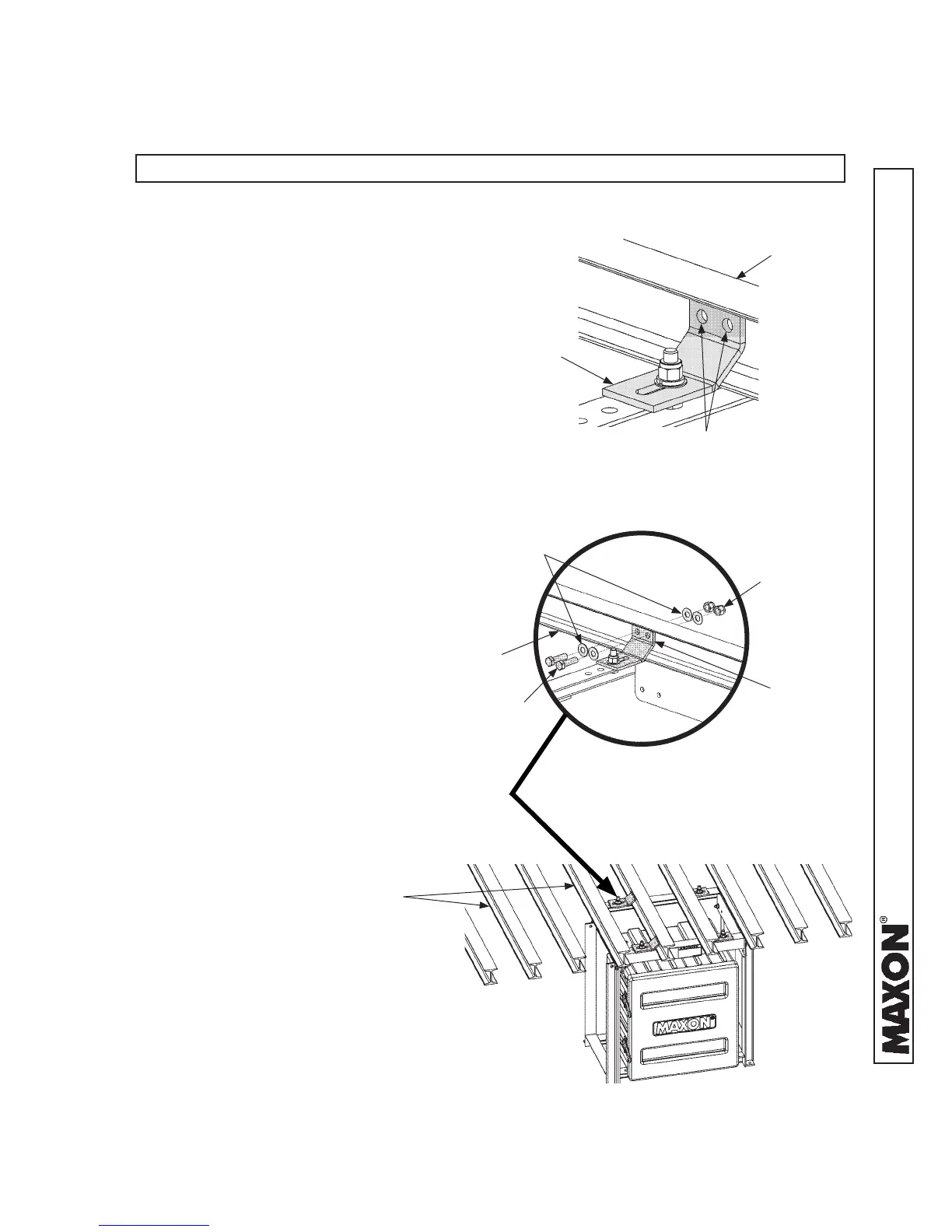
STEP 3 - ATTACH OPTIONAL BATTERY BOX & FRAME
TO VEHICLE (IF EQUIPPED) - Continued
NOTE: If welding mounting brackets to cross members, skip instruction 3.
3. Using mounting brackets as a tem-
plate mark and drill holes through
cross members (FIG. 26-1). Bolt
mounting brackets to cross mem-
bers as shown in FIGS. 26-2A and
26-2B. Torque bolts and lock nuts
to 85-128 lb-ft.
CROSS
MEMBER
CROSS
MEMBERS
MOUNTING
BRACKETS
1/2” HOLES
BOLTING BATTERY BOX FRAME
FIG. 26-2A
BOLTING BRACKETS
(8 PLACES)
FIG. 26-2B
CROSS
MEMBER
CAP SCREWS
(2 PLACES)
WASHERS
(4 PLACES)
LOCK NUTS
(2 PLACES)
MOUNTING
BRACKETS
MARK AND DRILL BRACKET HOLES
FIG. 26-1
 Loading...