11921 Slauson Ave. Santa Fe Springs, CA. 90670 (800) 227-4116 FAX (888) 771-7713
46
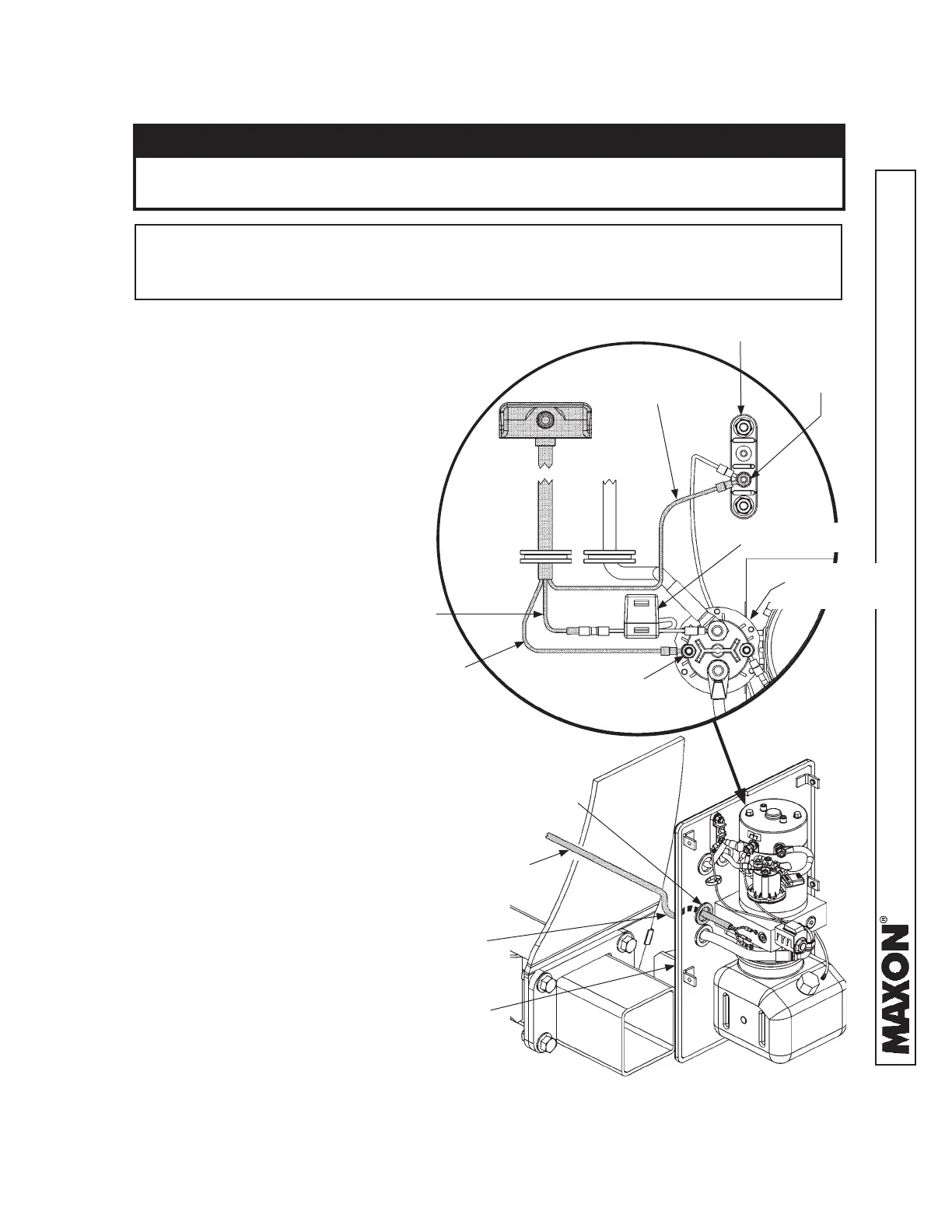
STEP 7 - INSTALL CONTROL SWITCH - Continued
NOTE: Hydraulic lines and electrical lines run into pump box through sealing grom-
mets (FIG. 46-1). To ensure a good seal on hydraulic & electrical lines,
never cut the sealing grommets.
CONTROL SWITCH CONNECTED TO
GD PUMP ASSEMBLY
FIG. 46-1
PUMP MOUNTING
PLATE
WIRING
HARNESS
GROMMET
5. Insert control switch switch wiring
harness through grommet on pump
mounting plate (FIG. 46-1). Con-
nect the switch wiring to the pump
assembly as shown in FIG. 46-1.
JUNCTION BLOCK
TERMINAL-1
STARTER
SOLENOID
GREEN WIRE
WHITE WIRE
BLACK WIRE
FUSE HOLDER
COIL DRIVE (+)
(#10-32 NUT)
CAUTION
Do not over-tighten the terminal nuts. For the 5/16” load terminals, torque nuts
to 35 lb-in. Torque the nuts on #10-32 control terminals to 15 lb-in.
CAUTION
DRIP LOOP
6. Form a drip loop on the control
switch wiring harness where it
enters the grommet from out-
side the pump mounting plate
(FIG. 46-3).