11921 Slauson Ave. Santa Fe Springs, CA. 90670 (800) 227-4116 FAX (888) 771-7713
45
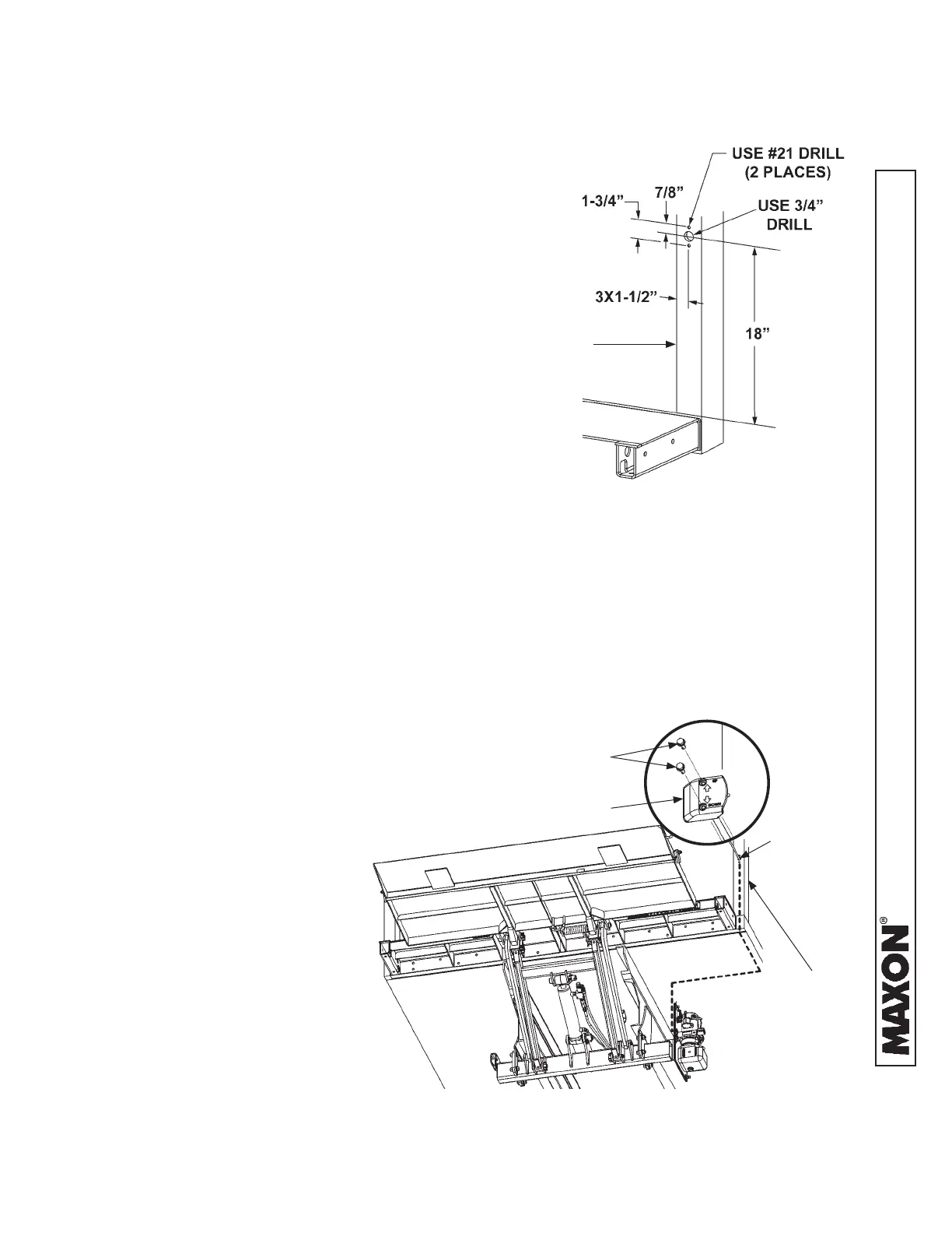
STEP 7 - INSTALL CONTROL SWITCH
DRILLING MOUNTING HOLES
FIG. 45-1
1. Measure, mark and drill one 3/4“ hole and two
#21–size holes in the vertical post on curb side
of vehicle body as shown in FIG. 45-1.
VEHICLE BODY
VERTICAL POST
(CURB SIDE)
ROUTING CONTROL SWITCH WIRING
FIG. 45-2
2. Insert control switch wiring (parts
box) into the 3/4” hole on the
corner post, down the corner post,
and under the vehicle body to the
pump assembly.
(See dashed line - FIG. 45-2.)
3. Push control switch and cable
back into the 3/4” hole in the verti-
cal post until control switch touch-
es the post (FIG. 45-2). Attach
control switch to vertical post with
2 self-tapping screws (parts box)
(FIG. 45-2).
4. If necessary, use
clamps and self-tapping
screws (parts box) to
secure switch cable to
vehicle under-body and
frame (FIG. 45-2).
VEHICLE BODY
VERTICAL
POST
CONTROL SWITCH
#10-24 X 1-1/2” LG.
SELF-TAPPING
SCREWS
3/4” HOLE