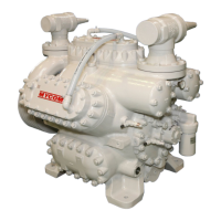
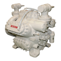
Reciprocating Compressor M Series
3-8
Note 4: When the belt is under the minimum tension load, make sure that the belt does not move excessively by operation, because the
load fluctuates due to the load conditions.
z After replacing the belt, operate the compressor for 2 to 3 hours, initial tension and friction will
occur on the new belt. Due to these and other causes such as peel-off of coating from flywheel,
the tension load of belts may decrease drastically to less than the minimum. If the belt is
continuously used in this condition, the service life of belt will be shortened by slipping. In
addition to this, defects may occur such as excessive movement of belt, overturn and deviation
caused by wear of belt on one side. Make sure to re-tighten the belt soon after operation.
z If the belt is replaced with a new one, operate the compressor with the new belt for 24²48 hours
and check the tension again.
Centering and Installation of Couplings
The installation positions of the compressor and motor are a product of the center distance of the couplings. Also,
the difference of center core heights is within 0.1mm(0.0043 inches) by machining process of frames.
To align the center shafts, correct the vertical and horizontal deviations.
1. Attach the coupling hub on the compressor side to the crankshaft.
2. Set the dial indicator on the motor axle using a magnetic stand or others, so that the probe contacts the
external diameter and surface of the coupling hub on the compressor side.
Fig. 3-5 Measurement of axle core
Symbol Description No. Description
A Measurement of core deviation 1 Dial indicator
B Measurement of angle deviation
3. Read the scale of dial while rotating the motor axle. Then adjust the coupling hub by moving the motor so
that the core runout of external diameter (core deviation) is 0.06mm(0.0023 inches) or less, and the
deflection of hub face (angle deviation) is 0.03mm(0.0012 inches) (standard: diameter of 100mm( 3.94
inches)) or less.
4. When the alignment is within the specified measurements, tighten the motor on the frame. Tighten the
flywheel, if any, on the hub on the compressor side with bolts.
5. Attach the coupling hub on the motor side to the axle.
Do not tighten it at this point.
6. Attach the coupling/insert to the coupling hub on the compressor side.
Insert bolts from the back of hub (on the compressor side), then attach washers, coupling/insert, washers,
and nuts in the described order.
The washers are processed to be curved on one side. This side should face to the coupling/insert.
7. Attach the spacers to the coupling/insert attached in step 6.
The large hole on the hub face of spacer is back clearance for the tightening nuts of coupling/insert on the
compressor side.