Reciprocating Compressor M Series
5-41
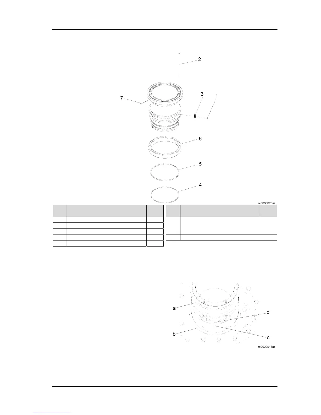
5.5.12 Cylinder Sleeve Assembly
Steps Description
Part
No.
Steps Description
Part
No.
1
Stop ring, lift pin
70 6
Cam ring
62 or
2
Lift pin
68
(Refer to "Assembly of the Cam Ring".)
63
3
Spring, lift pin
69
4
"O"ring, cylinder sleeve
67 7
Spring pin, cylinder sleeve
61-1
5
Retaining ring
65
1. Remove the parts in the order shown in the figure.
2. Attach the parts in the reverse order of removal.
5.5.12.1 Assembly of the Cam Ring
1. Verify the positions of the cylinder sleeve
positioning pin (a) and case groove (b), then
adjust the cam ring so that the cam ring notch (d)
is directly below (the side of bushing rod tab (c))
when the assembly is attached to the crankcase.