Reciprocating Compressor M Series
5-18
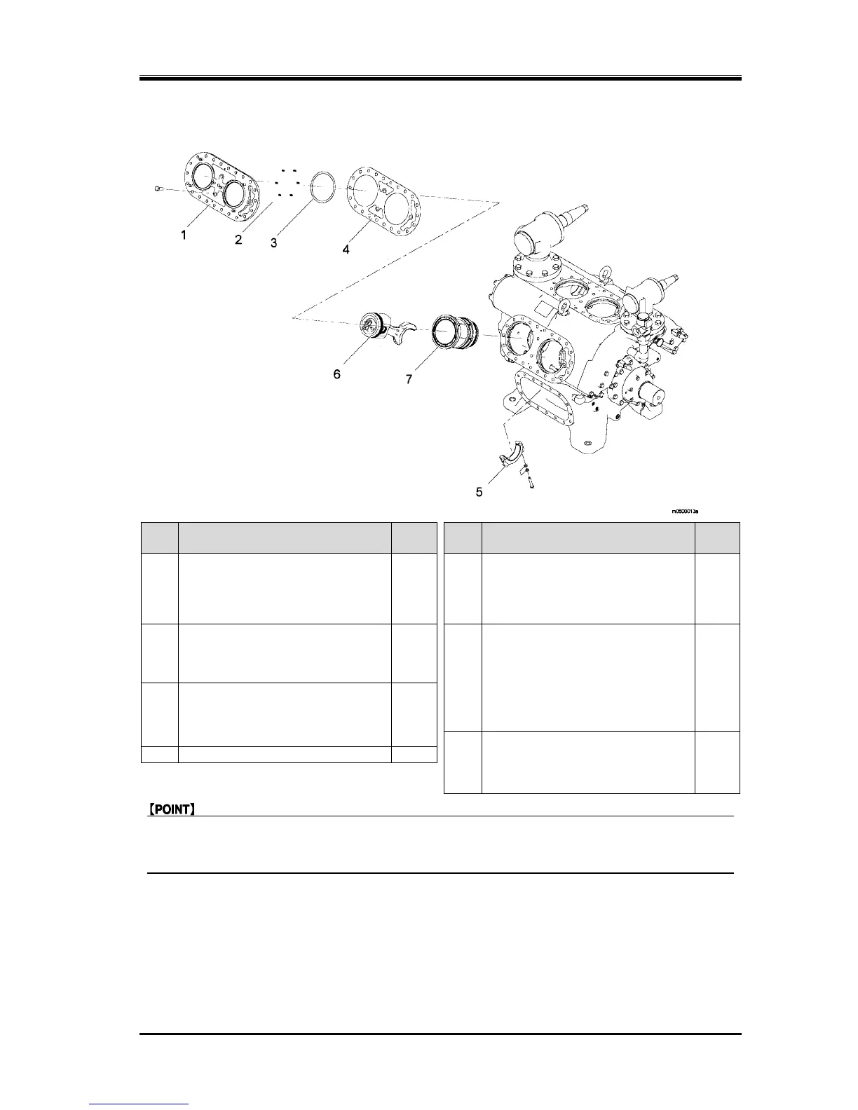
5.5.4 Valve Plate/Piston Assembly/Cylinder Sleeve Assembly
Steps Description
Part
No.
Steps Description
Part
No.
1
Valve plate
73 5
Connecting rod (rod cap)
77-S
(Refer to "Removing the Valve Plate".) (Refer to "Removing the Piston
Assembly".)
or
(Refer to "Attaching the Valve Plate".) (Refer to "Attaching the Piston
Assembly".)
77-L
2
Spring, suction valve
72 6
Piston assembly & connecting rod
(rod)
77-S
(Refer to "Attentions for Attaching the
Suction Plate Valve/Suction Valve
Spring".)
(Refer to "Removing the Piston
Assembly".)
or
3
Suction plate valve
71
(Refer to "Attaching the Piston
Assembly".)
77-L
(Refer to "Attaching the Suction Plate
Valve/Suction Valve Spring".)
(Refer to "Piston Assembly".)
7
Cylinder Sleeve Assembly
—
4
Gasket, valve plate
73-4
(Refer to "Attaching the Cylinder Sleeve
Assembly".)
(Refer to "Cylinder Sleeve Assembly".)
z For attaching the valve plate and cylinder sleeve, insert a spacer between the unloader piston
and unloader cover. The valve plate and cylinder sleeve cannot be attached unless a spacer is
inserted between them.
1. Insert a spacer with thickness of 17—19 mm(0.66—0.75 inches) between the unloader piston and unloader
cover.
(Refer to "Attachment of the Spacer".)
2. Remove the parts in the order shown in the figure.
3. Attach the parts in the reverse order of removal.
4. Remove the spacer. (Refer to "Removal of the Spacer".)